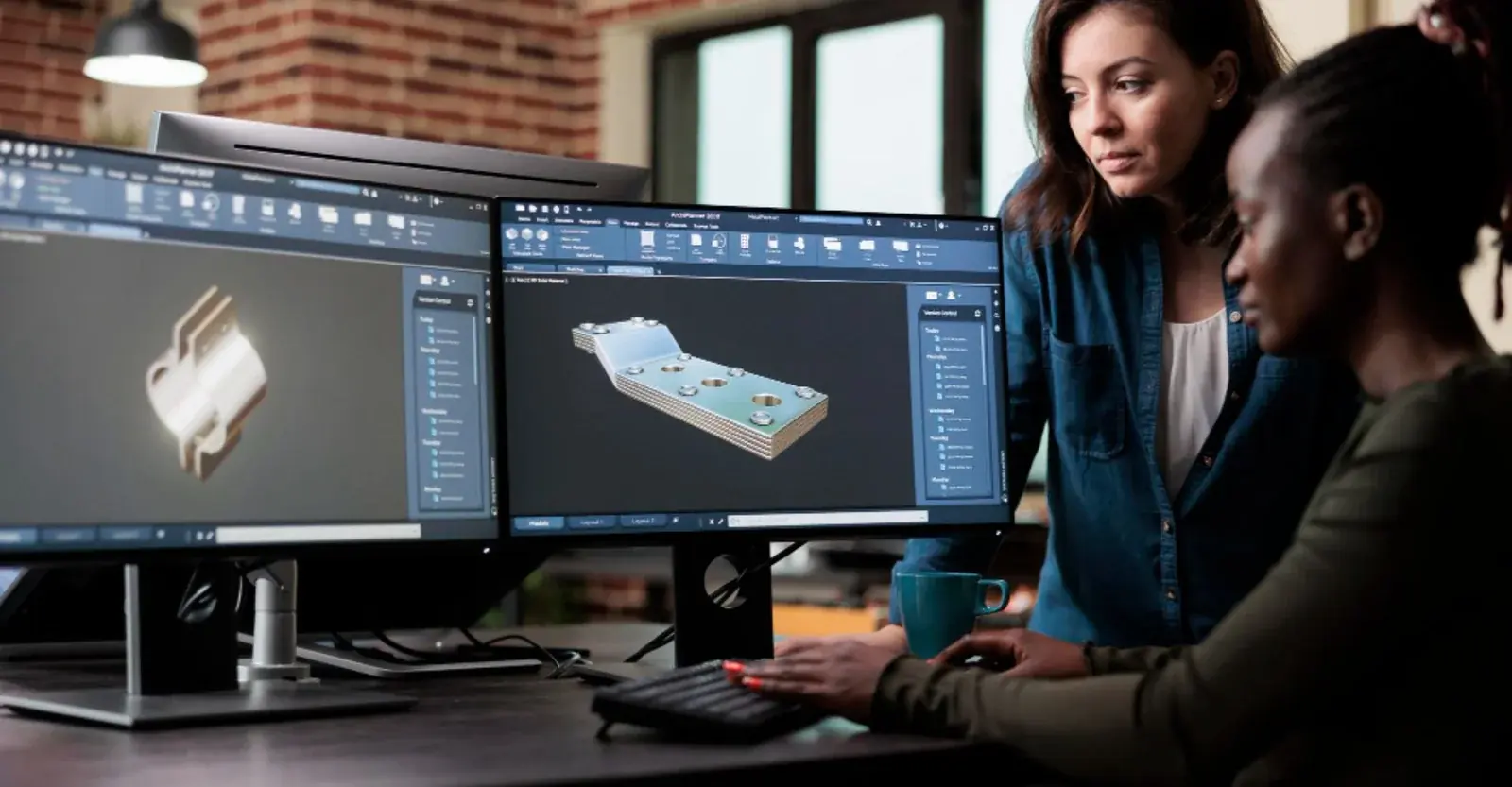
Industrial Enclosures & Cabinets
Equipment enclosures and cabinets developed around internal components, doors, mounting, access, ventilation, service entry, finish and the intended fabrication route.

Industrial sheet metal engineering
Mechanical engineering for industrial enclosures, guards, panels, brackets, chutes, weldments and heavy gauge fabrications. Fabrixon connects material and forming decisions with assembly interfaces, flat patterns, drawings, DXF files, BOMs and controlled supplier handover.
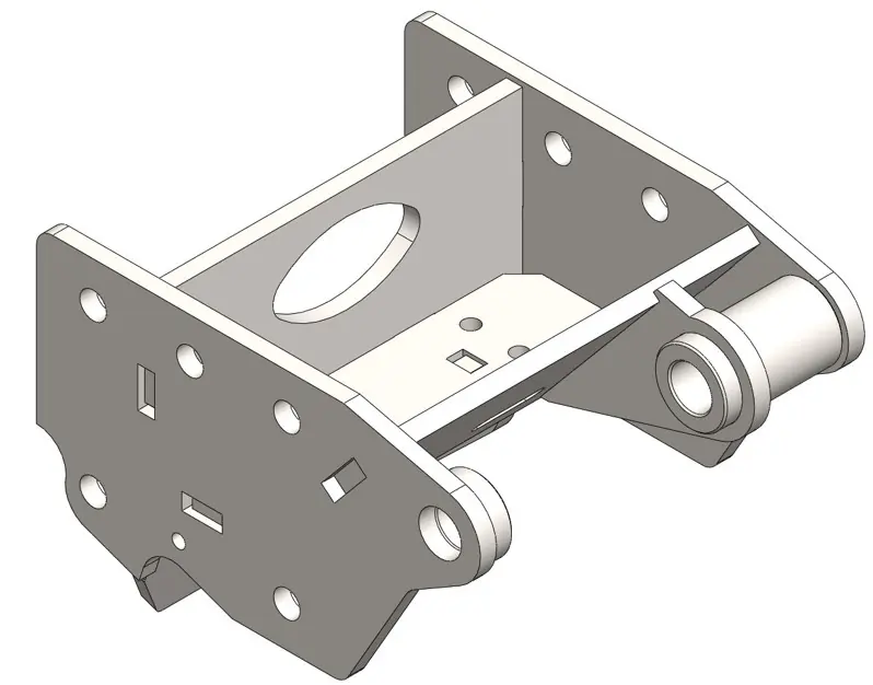
Machinery, fabricated assemblies, technical drawings, validation and supplier coordination
Sheet metal parts, assemblies, drawing packages and supplier release documentation
Enclosures, guards, formed parts, weldments, flat patterns and heavy gauge design
From fabrication basis through controlled manufacturing documentation
Sheet metal engineering capabilities
From an individual formed component to a complete enclosure or fabricated assembly, the engineering is developed around function, material, gauge, forming method, joining, access, surrounding interfaces and the supplier process used to manufacture the parts.
Integrated sheet metal programme
Material and gauge, bend rules, interfaces, joining, tolerances and manufacturing outputs are developed around the same functional requirement. CAD, flat patterns, drawings, DXF files, BOMs and revision information remain aligned as the design changes.
Equipment enclosures and cabinets developed around internal components, doors, mounting, access, ventilation, service entry, finish and the intended fabrication route.
Machine guards, covers, skins and access panels developed around equipment interfaces, maintenance access, panel stiffness, hinges, latches and agreed safeguarding requirements.
Formed components developed around load, product flow, mounting, stiffness, drainage, clearances, access and practical bend geometry.
Welded sheet metal and mixed fabrication assemblies developed around force transfer, joint architecture, weld access, distortion, tolerances and assembly sequence.
Controlled flat patterns and shop files prepared from agreed material, gauge, bend allowance or deduction data, relief rules and supplier forming information.
Load-bearing formed plates, chassis components and heavy gauge fabrications developed around structural behaviour, stiffness, joining and available forming processes.
Common sheet metal risks
Sheet metal projects usually encounter avoidable rework when the fabrication method, bend basis, assembly interfaces or manufacturing information are not resolved early enough.
Material, gauge, bend radius, tooling, reliefs, joining, finish or available supplier processes may still be uncertain when detailed geometry begins.
Generic bend settings, missing supplier data or inconsistent model rules can create dimensional errors after cutting and forming.
Fastener and weld access, cable routing, door swing, service clearances, tolerance stack or distortion can expose problems during fabrication and assembly.
Bend direction, datums, tolerances, weld information, finish, flat patterns, DXF files, BOMs or revision status may not agree with the controlled model.
Engineering approach
Useful sheet metal engineering goes beyond creating a folded model. Material behaviour, supplier capability, joining, tolerances, assembly and shop-file control are connected through the programme.
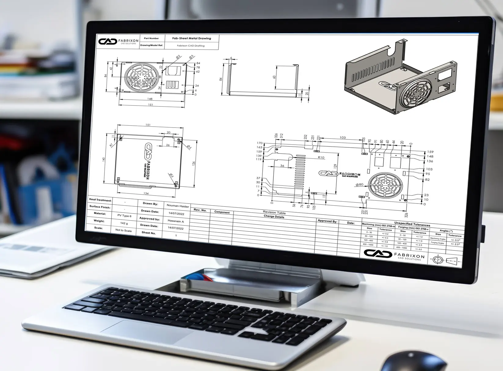
Part or assembly function, interfaces, material, gauge, finish, quantity, supplier process, bend data and acceptance requirements.
Panels, flanges, returns, doors, guards, stiffeners, mounting features, joining strategy, access and surrounding equipment interfaces.
Bend radius, reliefs, minimum flanges, fasteners, tabs and slots, weld access, tolerance strategy, hardware and assembly sequence.
Supplier bend tables or validated bend rules, tolerance review, DFM, load calculations and FEA where they reduce uncertainty and support a design decision.
CAD, drawings, flat patterns, DXF files, BOMs, assumptions, revision status and supplier clarification information issued as one coordinated package.
Selected sheet metal work
Selected trailer engineering projects illustrating fabricated assemblies, formed components and controlled manufacturing documentation.
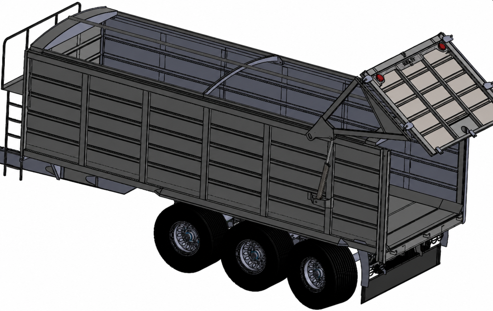
Engineering development of a triaxle silage trailer from legacy 2D layouts through 3D design, hydraulic rear gate integration, structural FEA, European type approval support and manufacturing documentation.
View case study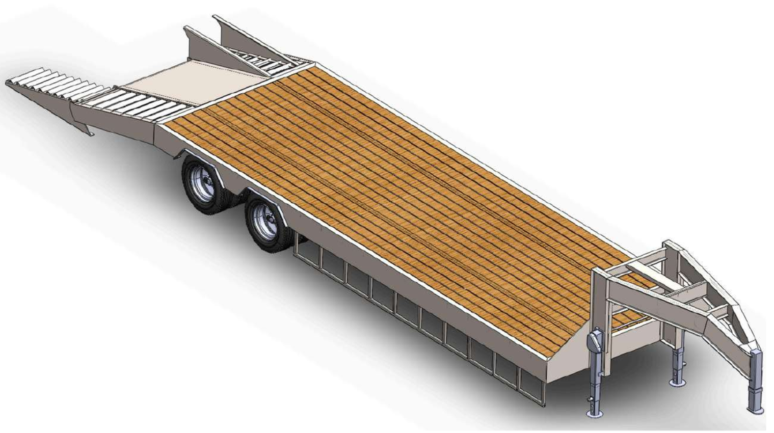
Parametric structural engineering of a 40 ton gooseneck lowbed trailer family with FEA led reinforcement, movement envelope checks and manufacturing documentation.
View case study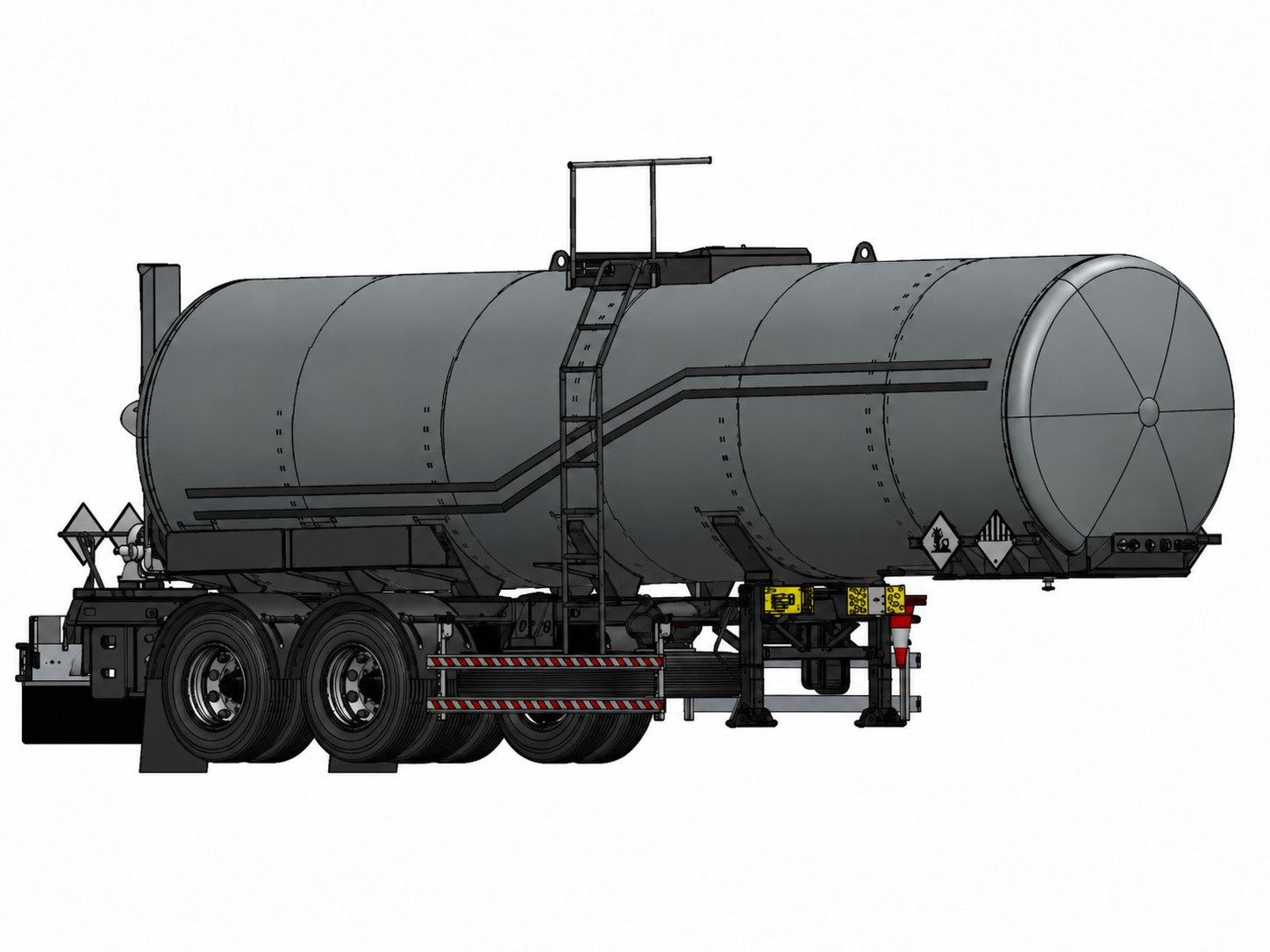
Integrated engineering of a 25,000 litre tanker vessel, tri axle chassis, CFD supported slosh control and pressure and discharge system packaging.
View case studySpecialist engineering review
Sheet metal is reviewed as part of the fabricated product and surrounding assembly, not as isolated folded parts. The objective is to challenge the assumptions most likely to affect forming, fit, joining or supplier release.
Review of material and gauge, bend data, tooling limits, minimum features, reliefs, finish, expected quantities and the process information needed before flat patterns are released.
Review of fasteners, welds, hinges, latches, datums, tolerance stack, service clearances, door movement, distortion and the relationship with adjacent equipment.
Review of drawing completeness, flat patterns, bend information, DXF outputs, BOMs, assumptions, revision status and supplier clarification requirements.
Typical deliverables
The deliverable package is agreed around the component, fabrication process and supplier responsibilities so models, shop files and drawings remain aligned for review and handover.
CAD · drawings · flat patterns · DXF files · BOMs · revision control
Controlled part and assembly models with sheet metal features, interfaces and agreed native or neutral CAD outputs.
Part, assembly and weldment drawings with agreed dimensions, tolerances, joining information, notes and revision status.
Flat patterns, bend direction, bend tables or notes, relief information and the agreed material and forming basis.
DXF files and agreed STEP, PDF or drawing exports prepared with controlled naming and project-specific file information.
Manufactured parts, material grades, gauges, finishes, purchased hardware and relevant supplier references.
Assumptions, open actions, interface notes, change records, agreed manufacturing files and supplier clarification information.
How engagements work
A clear engagement path keeps the fabrication basis, interfaces, assumptions and required outputs defined without turning the page into a process manual.
Send sketches, CAD, drawings, photographs, prototypes, supplier information or details of the surrounding assembly.
Agree function, material, gauge, forming data, joining, finish, tolerances, interfaces, required outputs, review points and responsibilities.
Engineering progresses through defined technical reviews, with bend, assembly, DFM, tolerance and validation issues raised as they surface.
Models, drawings, flat patterns, DXF files, BOMs and agreed records are issued under revision control with supplier clarification support as scoped.
Useful starting inputs: part or assembly function, interfaces, material and gauge preferences, finish, quantities, existing CAD or drawings, supplier capabilities, bend data where available and the outputs your team needs.
Buyer questions
Direct answers to the technical and commercial questions that most often determine whether a sheet metal project can be scoped correctly.
The scope can include material and gauge definition, 3D sheet metal CAD, enclosures, guards, panels, brackets, trays, chutes, weldments, heavy gauge fabrications, flat patterns, bend information, manufacturing drawings, DXF files, BOMs and supplier handover. The exact package depends on the starting information, fabrication process and responsibilities agreed for the project.
A complete specification is not required. Useful starting information includes the part or assembly function, product or equipment interfaces, material and gauge preferences, expected quantities, finish, environment, existing CAD or drawings, supplier capabilities, bend data where available and the outputs your team needs. Missing inputs are identified during the initial engineering review.
Flat pattern accuracy depends on the material, gauge, bend radius, tooling and forming process. Fabrixon can work from supplier bend tables, bend deduction data, validated material rules or project specific test information. Generic software defaults are not treated as universally correct, and the agreed bend basis is recorded in the project information.
Yes. Flat patterns can be exported as DXF files with the agreed geometry, layers, bend lines, etch information and file naming. Final nesting, machine programming and process settings normally remain with the fabricator unless assigned separately.
Yes. Fabrixon can design industrial enclosures, cabinets, machine housings, guards, access panels, chutes, hoppers and fabricated assemblies. Rating, guarding and welding requirements can inform the mechanical design where specified, while final testing, certification, welding procedure qualification and statutory approval remain with the responsible manufacturer or authorised party.
Yes. Existing CAD, drawings, prototypes or fabricated parts can be reviewed for bend feasibility, tolerance, fastener and weld access, assembly sequence, flat pattern control, drawing completeness and revision status. Reusable work is retained and the unresolved design or documentation gaps are addressed within the agreed scope.
Cost and duration depend on the starting information, number of parts and assemblies, fabrication complexity, supplier data, tolerance requirements, drawing and DXF depth, review cycles and project interfaces. A defined component or drawing package may be shorter than a complete enclosure or fabricated assembly programme. Scope, assumptions, programme and commercial basis are confirmed in writing before work begins.
Next step
Share the sketch, CAD, drawings, prototype, supplier bend data or surrounding assembly information. An engineer will review the starting point and confirm the most practical design and documentation scope.
A brief outline is enough to start the conversation.