Static Stress & Deformation
Linear static assessment of components and assemblies for stress, displacement, stiffness, reactions and safety margin under defined operating, handling or test loads.

Finite element analysis & structural validation
Static and nonlinear structural analysis for machinery, equipment frames, weldments, bolted assemblies and load bearing components. Fabrixon builds the model around realistic loads, restraints and interfaces, then interprets the results against a defined engineering decision.
Mechanical design, structural behaviour, FEA, validation and technical reporting
Structural analysis programmes acrossmachinery, frames, weldments, joints andload bearing components
Static, frames, joints, buckling, nonlinear response and controlled design comparison
From engineering question and load basis through interpreted evidence and controlled handover
Structural analysis capabilities
From a single load bearing component to a fabricated machine frame or nonlinear assembly, the model is built around the real load path, interfaces, material behaviour and the decision the analysis must support.
Defensible structural validation
Loads, restraints, materials, contacts and acceptance criteria stayconnected as model fidelity increases. Mesh refinement, sensitivity checksand engineering interpretation are applied where they can changethe conclusion, not simply to create a more detailed contour plot.
Linear static assessment of components and assemblies for stress, displacement, stiffness, reactions and safety margin under defined operating, handling or test loads.
Structural assessment of machinery frames, chassis, supports and fabricated assemblies, including global load path, local plate behaviour, reactions and critical joints.
Fastener forces, preload assumptions, separation, slip, bearing and contact pressure where joint and interface behaviour governs the assembly response.
Eigenvalue screening and, where justified, nonlinear stability assessment for compression loaded members, plates, panels and shells.
Large deflection, changing contact or material plasticity where linear assumptions no longer represent the governing structural behaviour.
Controlled comparison of geometry, thickness, material, stiffeners and joint arrangements using the same load basis so design changes can be judged consistently.
Common validation risks
Structural FEA creates value when it resolves a real design, release or failure question. These are the situations where a defensible model and clear engineering interpretation matter most.
Forces may be inherited, estimated or applied without a traceable connection to equipment duty, supports, interfaces and credible operating cases.
Constraints, contacts, mesh density or local singularities can dominate the result without representing the physical structure.
Cracking, distortion or excessive movement can expose a missed load path, stiffness issue, interface condition, joint response or instability mode.
Technical and compliance reviews need a traceable question, assumptions, model basis, sensitivity, interpretation, limitations and design action.
Engineering approach
The solver is only one part of the work. The analysis method is selected around the structural decision, with model detail increased only where it can materially change the conclusion.
Define the concern, operating and exceptional cases, acceptance criteria, required evidence and the decision the analysis must support.
Review geometry, material data, supports, contacts, fasteners, load origin, simplifications and any inputs that still require confirmation.
Choose element type, idealisation, joint representation and linear or nonlinear treatment to match the governing behaviour without unnecessary complexity.
Review mesh stability, reactions, load path, local peaks, deformation, contact and assumptions that can change the engineering conclusion.
Connect the results to the acceptance basis, explain limitations and provide the recommended change, comparison or release decision under controlled revision.
Selected structural work
Representative projects showing structural validation, FEA led redesign and load path assessment across trailers, heavy equipment and instrumented mechanical products.
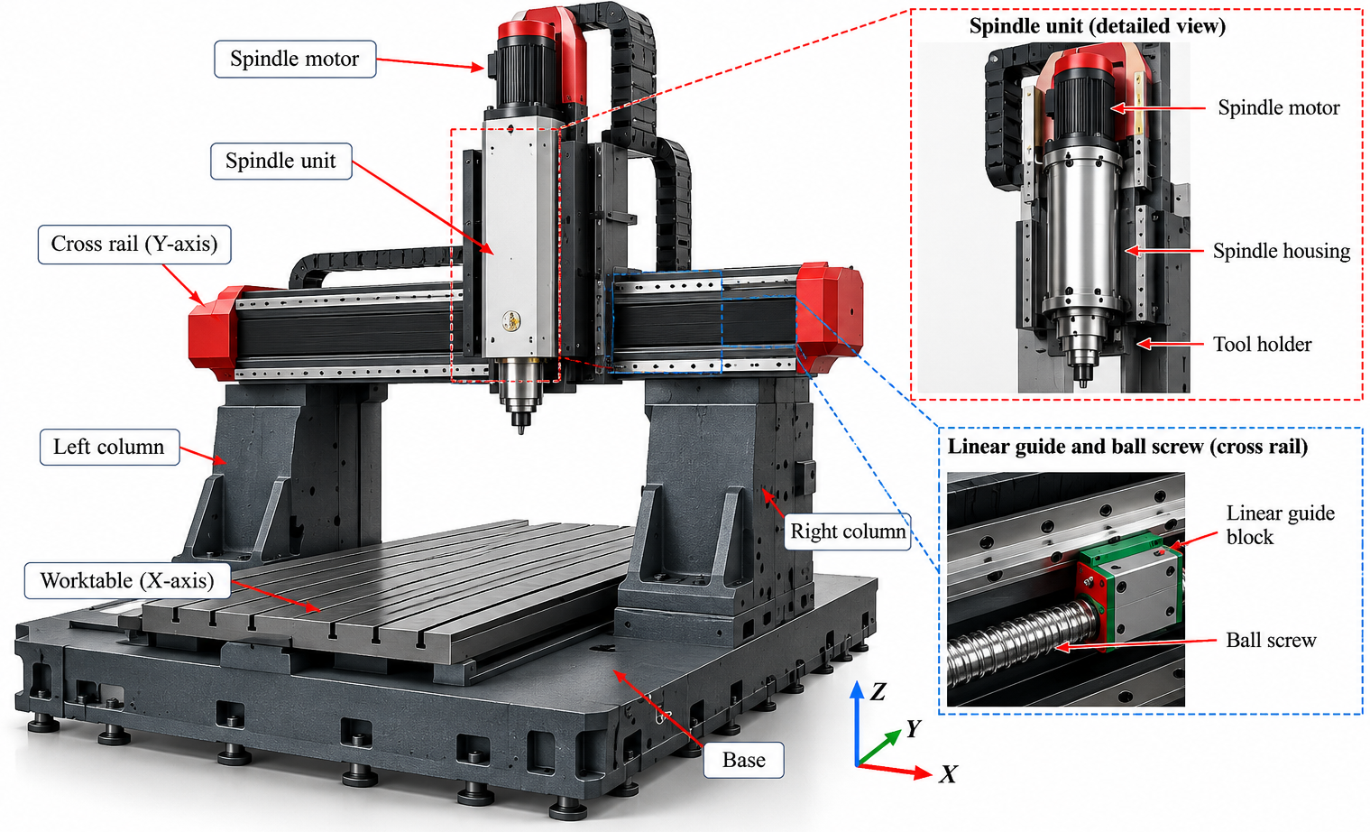
Case study showing how structural FEA, physical stiffness testing and optimization were combined to identify flexible machine regions and guide a lighter, better supported redesign.
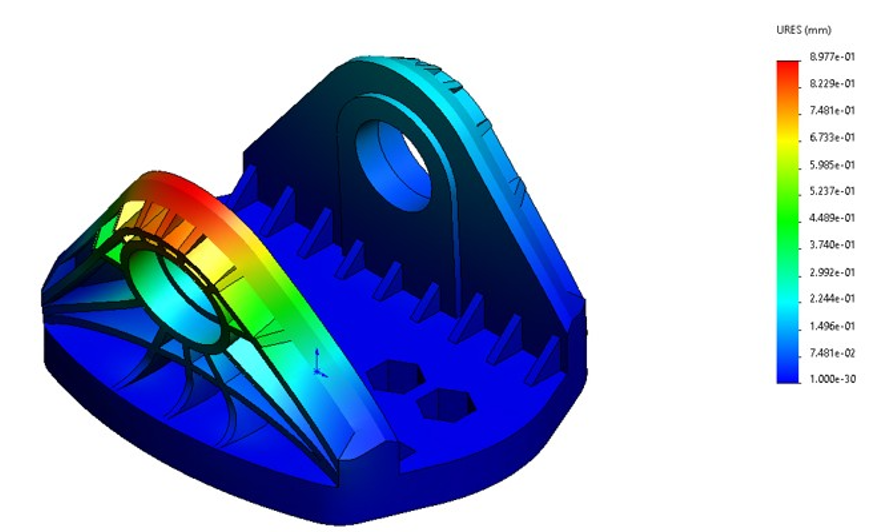
View case studyGeometry iteration and repeat static FEA reduced the reported peak stress by 48% within fixed hitch interfaces.
View case study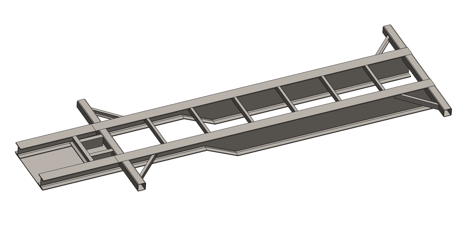
Static FEA of an OEM supplied gooseneck chassis with documented load assumptions, mesh refinement and design release evidence.
View case studyAnalysis reporting
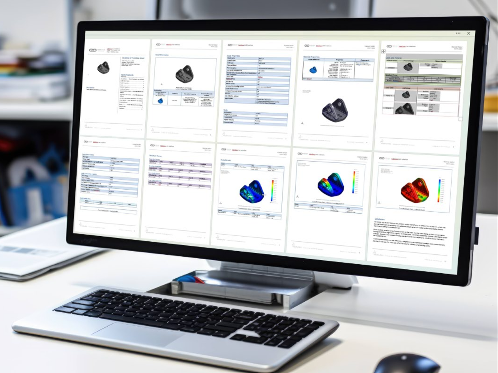
A contour plot is not a technical conclusion. The review must let another engineer trace the question, model basis, sensitivity, interpretation and recommended action and understand what the analysis does and does not establish.
Geometry idealisation, material data, load origin, constraints, contacts, acceptance criteria and open assumptions are recorded rather than left implicit.
Critical values are interpreted against the surrounding field, mesh sensitivity, load path and model limitations so a numerical peak is not mistaken for a physical failure.
The report can support client and compliance review, but it does not by itself certify the product. Review authority, specialist code checks and remaining validation responsibilities stay explicit.
Typical deliverables
The package is defined around the structural question, agreed load cases, model fidelity, acceptance basis and next design action so assumptions, solver evidence, conclusions and revisions remain connected.
Analysis basis · solver model · results · recommendations · controlled report
Revision controlled record of the engineering question, model basis, results, limitations, conclusions and recommended actions.
Operating and exceptional loads, support conditions, combinations, source information, acceptance criteria and open inputs requiring confirmation.
Model idealisation, material properties, joint and contact treatment, element selection, local refinement and sensitivity evidence relevant to the conclusion.
Critical plots, values, locations, reactions, contact or buckling behaviour and the engineering interpretation that governs the decision.
Variant comparison, recommended geometry or joint changes, remaining risks and the evidence supporting the selected direction.
Agreed solver files, result extracts, animations, review images and controlled issue records where included in the work package.
Analysis workflow
A four stage workflow keeps the engineering question, model basis, sensitivity and next design action visible without turning the analysis into a black box solver exercise.
Confirm the concern, operating cases, acceptance criteria, required evidence and the decision the analysis must support.
Review geometry, materials, interfaces, supports, contacts, load origin, simplifications and missing inputs before solving.
Apply the appropriate linear, contact, buckling or nonlinear method, then review mesh stability, reactions, local peaks and governing behaviour.
Issue controlled evidence, limitations, design comparison and the recommended change or review decision within the agreed responsibility route.
Buyer questions
Direct answers to the technical and commercial questions that usually determine whether a structural FEA scope can be defined correctly.
The scope can include linear static stress and deformation analysis, safety margin assessment, weldment and frame analysis, bolted connection and contact assessment, buckling screening, nonlinear static analysis and comparison of design alternatives. The work package records the geometry basis, materials, loads, constraints, mesh strategy, assumptions, results, limitations and recommended design actions.
Useful starting information includes a 3D model or drawings, material grades, operating and exceptional loads, mounting and support conditions, contact or fastener details, relevant standards, target safety factors or allowable limits and the design decision the analysis must support. Fabrixon identifies missing inputs during the initial model review.
Loads and constraints are derived from the real equipment duty, load path, supports, interfaces and operating sequence. The model records where each load originates, how it is distributed, which degrees of freedom are restrained and which simplifications have been made. Where the load basis is uncertain, sensitivity cases can be used to show how the conclusion changes.
Mesh refinement is concentrated where geometry, contact or load transfer makes the result sensitive. Fabrixon reviews element quality, result stability and the behaviour of stress through the surrounding region. A local peak caused by a sharp corner, point load or idealised restraint is not treated as a physical failure without engineering interpretation.
Yes. Welded frames, fabricated assemblies, bolted connections and contact interfaces can be included where the available geometry and input data support the required model. The analysis may consider global frame behaviour, local plate stress, support reactions, bolt forces, preload assumptions, separation, slip, bearing and contact pressure. Detailed weld or fastener code checks are defined separately where required.
FEA can provide documented engineering evidence for design reviews, client requirements and defined compliance submissions, but an analysis report does not by itself certify a product. The applicable code basis, acceptance criteria, design responsibility and review authority must be agreed before work begins. Pressure equipment and other specialist code scopes are considered only when the required code route and suitably qualified review are clearly defined.
Cost and duration depend on model quality, number of load cases, contact and joint complexity, material behaviour, mesh sensitivity, nonlinear requirements, acceptance criteria, redesign cycles and reporting depth. A defined component with clear inputs may be assessed quickly, while a large assembly or nonlinear model requires a staged programme. Scope, assumptions, programme and commercial basis are confirmed before analysis begins.
Start with the engineering question
Share the model, load information, material data, support conditions and the concern that must be resolved. Fabrixon will review the starting point and define the analysis route, missing inputs and evidence needed for a defensible conclusion.