Stress Life Fatigue
Life assessment for components that remain predominantly elastic through repeated loading, including mean stress and applicable surface, size or notch effects.

Fatigue analysis & durability validation
Fatigue and durability analysis for machinery, equipment frames, weldments and mechanical components exposed to repeated loading. Fabrixon connects the structural response, operating duty, fatigue data and damage method so the life prediction supports a clear engineering decision.
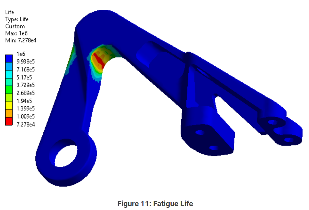
Mechanical design, structural behaviour, fatigue validation and manufacturing documentation
Durability programmes across machinery, frames, components and welded structures
Stress life, strain life, weld fatigue, variable loading, multiaxial response and design comparison
From required life and duty definition through fatigue assessment, sensitivity and controlled design action
Fatigue analysis capabilities
From a single cyclically loaded component to a welded frame or complex duty spectrum, the fatigue assessment is built around the required life, structural response, detail type, load history and fatigue data that govern the decision.

Duty led fatigue validation
Required life, cyclic loading, structural stress or strain, fatigue dataand damage method stay connected throughout the assessment.Sensitivity is added only where uncertainty in duty, data or localdetail can materially change the durability conclusion.
Life assessment for components that remain predominantly elastic through repeated loading, including mean stress and applicable surface, size or notch effects.
Assessment where local cyclic plasticity, high strain amplitude or lower cycle behaviour makes a purely elastic stress life route unsuitable.
Assessment of weld toes, roots and attachments using the fatigue route that best matches the detail, loading and governing reference.
Cycle counting, event weighting and cumulative damage assessment for realistic operating histories where amplitude, mean load or frequency changes through the duty.
Assessment of combined or changing stress directions where bending, torsion, axial load or non proportional loading cannot be represented by one scalar range.
Controlled comparison of geometry, weld detail, material, surface condition or duty changes so durability improvements can be judged clearly on one consistent fatigue basis.
Common durability risks
Fatigue analysis becomes valuable when required service life, repeated failure or variable duty cannot be resolved by a static stress result alone.
A component or assembly needs evidence against a defined number of cycles before manufacture, tooling or customer review.
Repeated operation can accumulate damage at a notch, interface, weld detail or stiffness transition even when each load event remains below general yield.
Weld toes, roots and attachments can govern durability even when the wider fabricated structure appears acceptable under static loading.
Amplitude, mean value, direction and event frequency may change across start, stop, payload, transport and operating conditions.
Engineering approach
A fatigue result is useful only when the repeated loading, required life and failure basis are defined clearly enough to support the model. Added complexity is used only where it can materially change the durability conclusion.
Agree the component, failure criterion, target cycles, acceptance route and the durability decision the assessment must support.
Translate operating states, measured histories or engineering load cases into representative events, cycles and spectra.
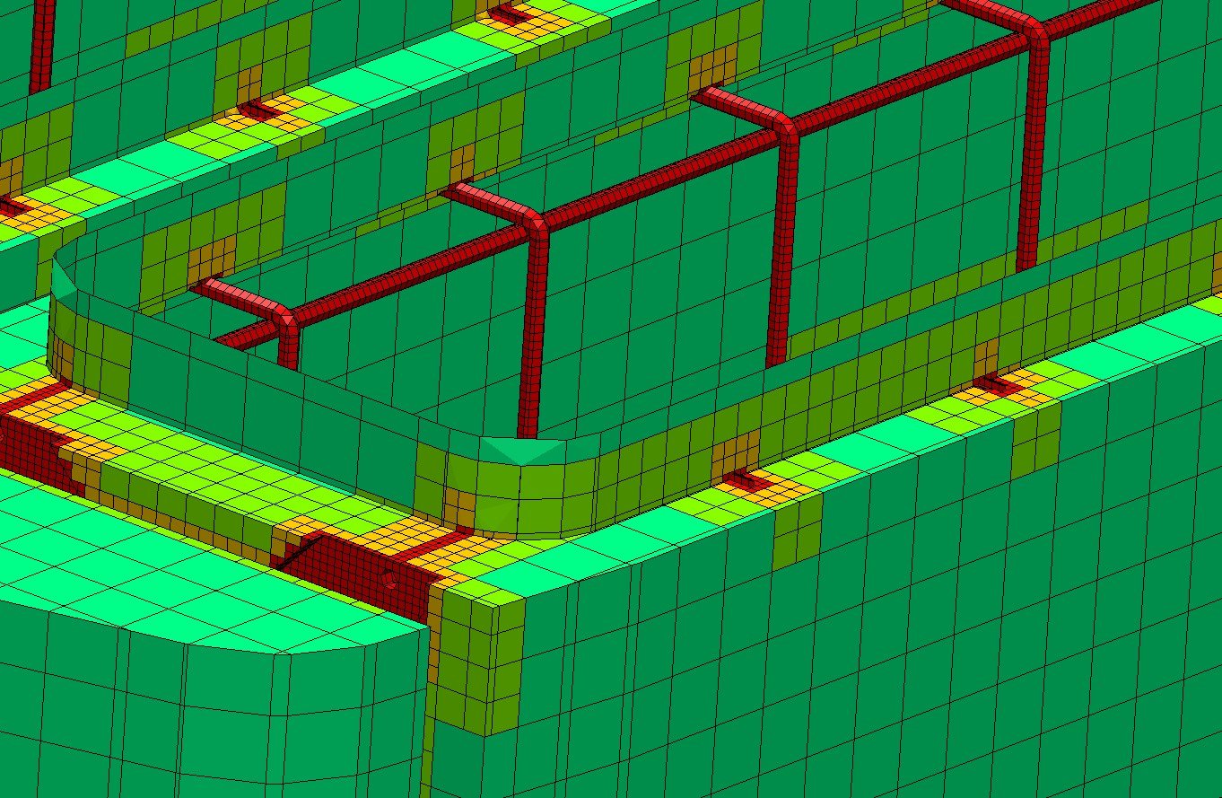
Prepare the structural model, loads, supports, contacts and local detail needed to establish the governing stress or strain range.
Match stress life, strain life, weld or multiaxial methods, fatigue curves and correction factors to the expected response and available evidence.
Translate critical locations, damage drivers, uncertain inputs and predicted life into a controlled design action or further validation requirement.
Representative fatigue applications
Representative application routes showing how the fatigue method changes with the structure, load history and likely failure mechanism.
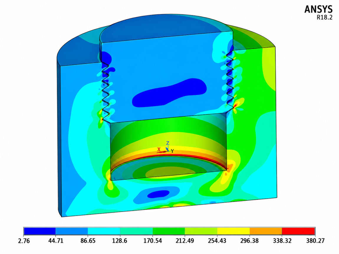
Industrial fatigue failure investigation using physical fracture evidence, measured operating loads, local FEA and probabilistic fatigue assessment.
View case study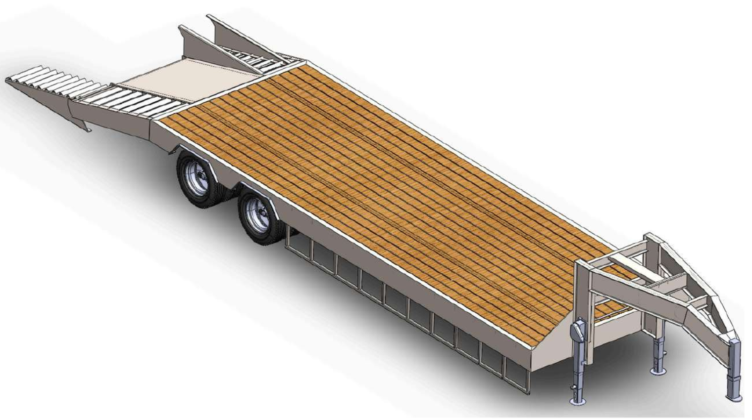
Parametric structural engineering of a 40 ton gooseneck lowbed trailer family with FEA led reinforcement, movement envelope checks and manufacturing documentation.
View case study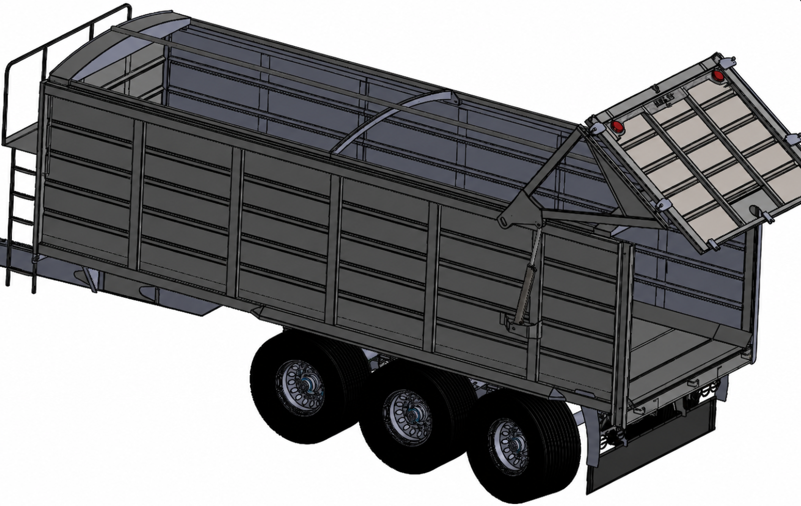
Engineering development of a triaxle silage trailer from legacy 2D layouts through 3D design, hydraulic rear gate integration, structural FEA, European type approval support and manufacturing documentation.
View case studyFatigue reporting
A fatigue life value is meaningful only when another engineer can follow the required life, duty history, structural response, fatigue data, corrections and damage method that produced it. Assumptions, sensitivity and limitations remain visible.
Operating states, event frequency, measured or derived histories, cycle counting, weighting and uncertain duty assumptions are recorded before damage is interpreted.
The structural response, fatigue curve, mean-stress treatment, surface or size effects, weld class and cumulative damage method are connected to the selected assessment route.
Predicted life is translated into a design decision without presenting the analysis as an unconditional guarantee of service life or product certification.
Typical deliverables
The package is defined around the required life, cyclic duty, structural response, fatigue method and next durability action so load records, life evidence, assumptions and revisions remain connected.
Duty basis · structural response · fatigue methodlife evidence · recommendations · controlled report
Revision-controlled record of the design life, duty basis, selected method, fatigue data, results, limitations, conclusions and recommendations.
Predicted life, cumulative damage, safety factor where applicable and the locations, events or assumptions that govern the conclusion.
Defined operating events, processed histories, cycle counts, event weighting and open duty assumptions requiring confirmation.
Material or weld curve, correction factors, stress or strain measure, cumulative damage method and references relevant to the assessment.
Damage concentration maps, baseline and revised life comparison and recommended geometry, weld, material or duty changes.
Agreed native solver files, cycle matrices, result extracts, animations or review images where included in the work package.
Analysis workflow
A four-stage workflow keeps the required life, duty basis, cyclic response, fatigue method and next durability action visible throughout the assessment.
Confirm the component, failure criterion, target cycles, operating events, load history and the design decision the assessment must support.
Build or review the structural model and establish the stress, strain or weld-detail response needed for the selected fatigue route.
Apply the fatigue data, corrections, cycle counting or multiaxial method, then test the inputs that could materially change the life conclusion.
Issue controlled life and damage evidence, limitations, critical locations and the recommended design or duty change.
Buyer questions
Direct answers to the technical and commercial questions that usually determine whether a fatigue life assessment can be defined correctly.
Fatigue analysis estimates how repeated loading can accumulate damage and limit the useful life of a component or welded detail. Depending on the problem, it can report predicted cycles to a defined criterion, cumulative damage, critical locations and sensitivity to duty or design changes. The result is an engineering estimate based on the load history, structural response, fatigue data and assumptions rather than an unconditional guarantee of service life.
Static analysis checks the response to a defined load event, while fatigue analysis evaluates damage accumulated through repeated loading. A component can remain below yield under each individual cycle and still develop a fatigue crack after enough repetitions. Fatigue assessment therefore requires cycle information, fatigue data and a defined life or damage criterion in addition to the structural stress result.
Useful inputs include a 3D model or drawings, material and manufacturing condition, weld details where relevant, operating loads, duty cycle or measured time history, number of cycles or required design life, support conditions, surface and environmental information and any known failure locations. Fabrixon identifies missing inputs and proposes sensitivity cases where the duty cannot be defined exactly.
Stress life methods use S N data and are generally suited to predominantly elastic response over a comparatively high number of cycles. Strain life methods use E N data and are considered where local cyclic plasticity or lower cycle counts affect the response. The method is selected from the expected behaviour, available data and decision that must be supported.
Welded joints are assessed using a method appropriate to the geometry, model detail and governing reference. This can include nominal stress, structural hot spot stress or effective notch stress methods. The selected fatigue class, stress extraction route, mesh requirements, weld toe or root location and thickness or mean stress treatment are documented in the report.
A variable load history can be reduced into cycles using a recognised counting method such as rainflow counting, then combined through a cumulative damage model where appropriate. When the stress direction changes materially within the cycle, a multiaxial method such as a critical plane or suitable equivalent stress approach may be required. The chosen method and its limitations are defined before life results are interpreted.
Cost and duration depend on model quality, structural analysis complexity, availability of a representative duty cycle, number of load histories, weld or material data, fatigue method, sensitivity studies, redesign iterations and reporting depth. A component with a clear load spectrum can be scoped quickly, while a large welded assembly or uncertain duty requires staged definition. The programme and commercial basis are confirmed after the initial engineering review.
Start with the engineering question
Share the model, material information, operating duty, required life and any known cracking or durability concern. Fabrixon will review the starting evidence, identify the missing inputs and define the fatigue assessment needed to support the next design decision.