
Triaxle Silage TrailerEngineering
Converted basic AutoCAD layouts into a coordinated 3D trailer design with weldment and sheet metal development, hydraulic rear gate integration, structural FEA, European type approval support and controlled manufacturing documentation.
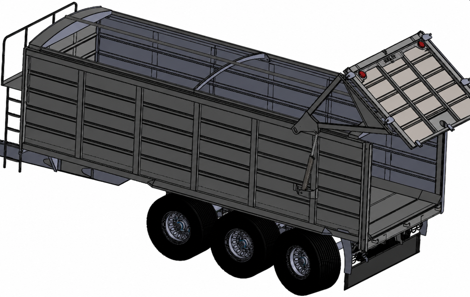
Develop a complete trailer system from limited 2D information
The client started with basic AutoCAD layouts but needed a coordinated triaxle silage trailer definition covering welded structure, sheet metal, rear gate hydraulics, vehicle interfaces, compliance documentation and manufacturing detail within an eight month development programme.
Structure
Develop the chassis, body weldments, floor, side walls, reinforcements and triaxle integration around the required load duty.
Hydraulics
Select and integrate the rear gate actuation arrangement with appropriate brackets, geometry and operating load capacity.
Approval support
Incorporate project specific European type approval requirements into vehicle layout and technical documentation.
Manufacture
Translate the developed design into controlled drawings and fabrication information that could support repeat production.
Integrate structure, body and running gear
The 2D concept was rebuilt as a complete 3D assembly. The work included detailed weldment structures for the main frame, sheet metal floor and side wall development, reinforcement geometry and integration of the triaxle suspension and chassis interfaces.
- Main structure
- Trailer frame and weldment architecture developed from the client layouts into a controlled 3D assembly.
- Body panels
- Floor and side wall sheet metal developed with bend and reinforcement features suitable for the trailer body structure.
- Running gear
- Triaxle suspension and chassis interfaces coordinated within the complete assembly rather than as isolated subcomponents.
- Design intent
- Model relationships were used to resolve interfaces before the manufacturing drawings were released.
Size the gate actuation around the operating load and mechanism geometry
The rear gate system was developed from the required lift duty and operating cycle. Hydraulic rams were selected around the gate load, then mounting brackets, cylinder positions and the associated hydraulic layout were coordinated with the trailer body.
Ram capacity
The project record specifies custom selected hydraulic rams with a 4 ton lifting capacity.
Load basis
Gate weight and operational loads were considered when defining the actuator requirement.
Mounting geometry
Bracket geometry, cylinder positions and attachment points were coordinated with the body and rear gate structure.
Motion
The mechanism geometry was developed to provide smooth gate opening and closing through the required travel.
Hydraulic layout
Component layout and circuit requirements were documented for integration with the gate mechanism.
Safety
The source record states that safety mechanisms were incorporated into the rear gate system design.
Coordinate vehicle details against the approval programme
Fabrixon reviewed the project type approval documentation and incorporated design changes associated with European transport and safety requirements. The engineering package included vehicle layout changes, lighting and braking related interfaces and technical information for the client’s regulatory submission.
- Vehicle layout
- Structural and load distribution details were adapted around the approval programme requirements stated in the project record.
- Lighting
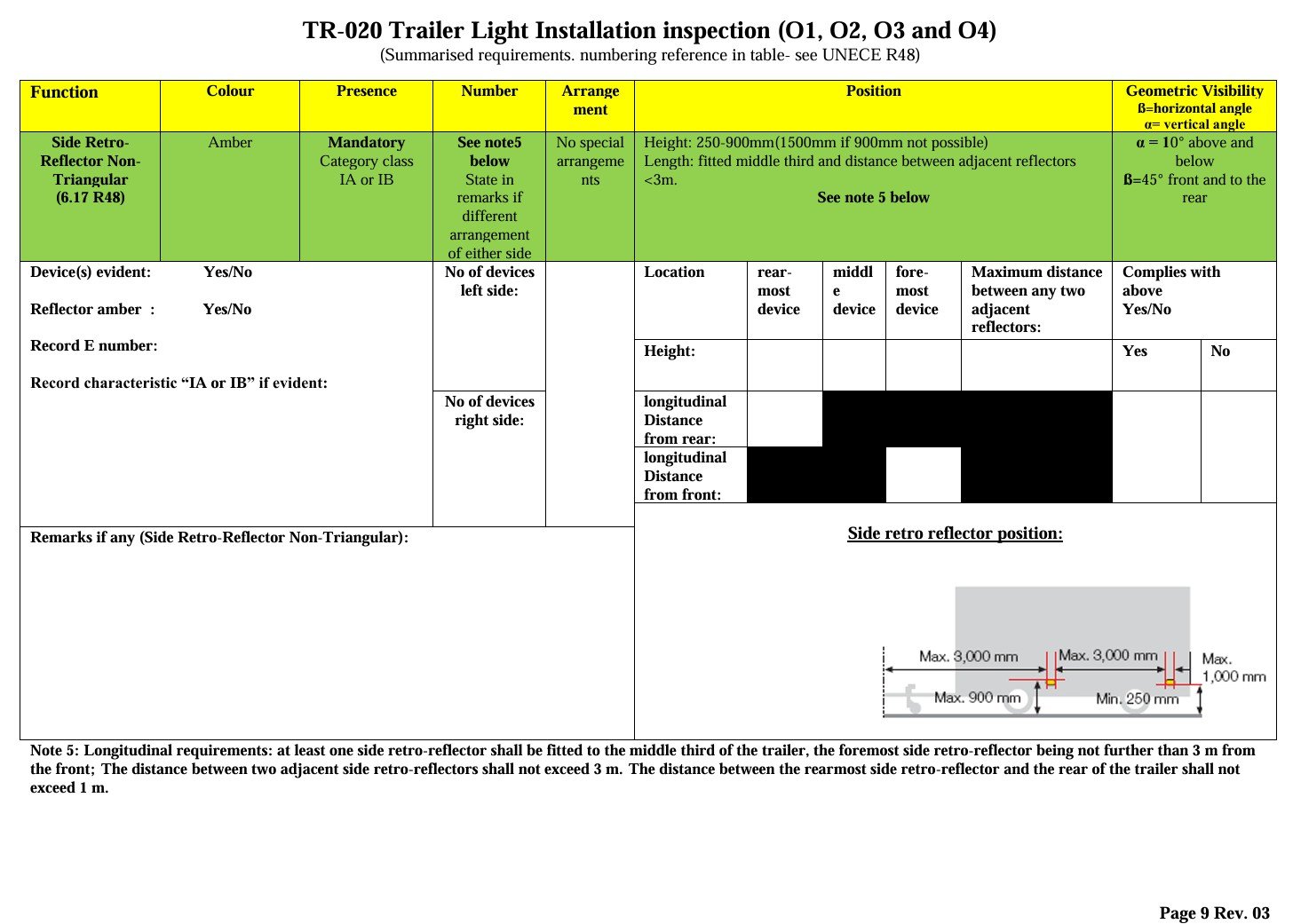
- The supplied inspection material includes a trailer lighting check referencing UNECE R48 requirements for side retroreflector positioning.
- Braking and safety
- Relevant vehicle system interfaces were coordinated within the design package for the European market configuration.
- Documentation
- Technical information was prepared to support the client’s type approval submission. No independent certification is claimed by this case study.
Validate the trailer chassis for the required payload and repeated loading
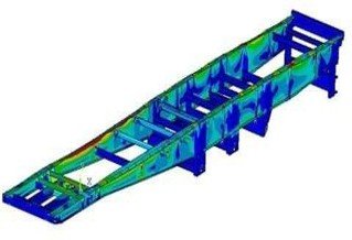
Structural FEA was used to review the chassis under the project loading conditions. The analysis covered the stated 35,000 lb payload, load distribution across the triaxle arrangement, welded joint behaviour and fatigue life for repeated operating cycles.
- Payload case
- Maximum load condition based on the stated 35,000 lb payload.
- Load distribution
- Reaction and load transfer reviewed across the triaxle configuration.
- Durability
- Weldment joint assessment and fatigue life prediction included in the project workflow.
- Safety checks
- Safety factor verification was included against the project acceptance criteria associated with the approval programme.
Convert the validated design into controlled fabrication documentation
The final engineering work included DFM review and manufacturing documentation for repeat fabrication. Welding access, standard material selection, component simplification and drawing control were used to reduce production effort without disconnecting the manufacturing package from the validated design.
- Weldments
- Fabrication details and reinforcement geometry developed for the chassis and body structural assemblies.
- Sheet metal
- Floor and side wall parts documented with the bends and geometry required for manufacture.
- Materials
- Standard materials and components were selected where practical to reduce cost and simplify sourcing.
- Assembly
- Complex assemblies were simplified to reduce production effort and support more repeatable build processes.
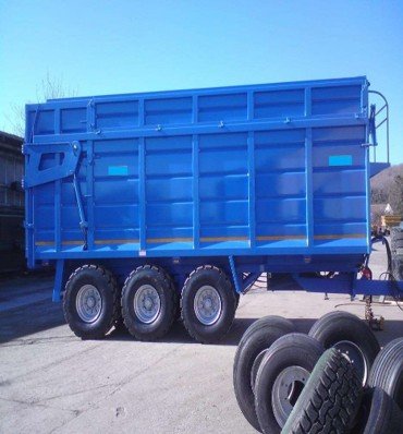
The completed trailer programme met the required operating and production duty
The source record reports successful manufacture and field deployment after the eight month engineering programme. The published project outcomes include first year production, manufacturing quality, material savings, development speed, payload and discharge performance.
Manufactured in the first year after the engineering programme.
Reported silage storage capacity for the completed trailer.
Project stated maximum load capacity used in the structural validation basis.
Reported complete discharge time for the finished trailer.
- Build quality
- The source record reports 94% of components manufactured correctly on the first attempt.
- Material cost
- 10% reduction reported through design optimization and standardization.
- Development
- 35% faster development than the traditional process stated in the project record.
- Field performance
- Zero structural warranty claims were reported for the first year production population.
- Launch
- Manufacturing reportedly started three months ahead of schedule for the target harvest season.
- Commercial impact
- The source records $150,000+ in first year benefits and approximately $1.12 million in first year revenue impact.
The trailer succeeded because structure, hydraulics, approval requirements and fabrication were developed together
The project was not a simple 2D to 3D conversion. The engineering value came from coordinating load paths, body construction, rear gate actuation, vehicle interfaces, approval documentation and manufacturing detail within one controlled development programme.
A complete trailer engineering package progressed into successful repeat manufacture
The completed project transformed preliminary 2D layouts into a coordinated trailer design supported by structural analysis, hydraulic integration, approval documentation and manufacturing release information. The source record confirms successful first year production and operating performance.
- Design package
- Complete 3D assembly definition covering chassis, body, reinforcements, sheet metal and triaxle interfaces.
- Validation
- FEA workflow included payload, load distribution, weldment and fatigue assessments.
- Compliance support
- Vehicle details and documentation coordinated around the client’s European type approval programme.
- Manufacturing
- Controlled drawings and fabrication information supported repeat build of the released design.
- Proven outcome
- 150 units were reported manufactured in the first year, with zero structural warranty claims in the project record.