Steady-State Thermal Analysis
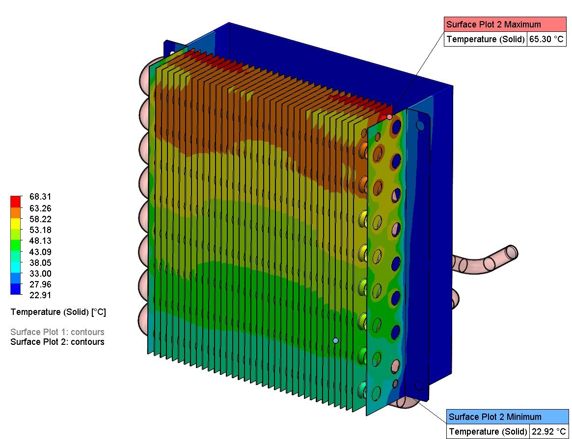
Equilibrium temperatures, heat flow, thermal gradients and hot spots under continuing operating conditions.

THERMAL PERFORMANCE VALIDATION
Thermal analysis for machinery, electronics enclosures, process equipment and heat transfer systems. Fabrixon connects heat sources, material data, conduction paths, convection, radiation and operating conditions so the temperature assessment supports a clear engineering decision.
THERMAL PERFORMANCE BEFORE RELEASE
Temperature limits. Heat flow. Cooling performance. Clear design actions.
Mechanical design, heat transfer, structural behaviour and industrial equipment validation
Design, analysis and thermal
validation projects across industrial
equipment and product development
Steady, transient, thermal structural,
enclosure cooling, conjugate heat
transfer and cooling performance
From heat source and boundary definition through solution, sensitivity and design action
Thermal analysis capabilities
From a defined component temperature check to coupled fluid solid heat transfer, the analysis route is selected from the governing heat path, operating duty, fluid influence and the engineering decision that must be resolved.
Thermal analysis capabilities
Heat sources, material properties, boundary conditions, cooling paths and coupled fluid behaviour remain connected throughout the assessment. Steady, transient, thermal structural or thermal CFD routes are added only when they materially change the engineering conclusion.
Equilibrium temperatures, heat flow, thermal gradients and hot spots under continuing operating conditions.
Warm-up, cool-down, thermal cycling and time-dependent temperature response during changing duty.
Expansion, differential growth, distortion, contact change and thermal stress driven by a temperature field.
Component dissipation, airflow paths, hot spots, recirculation, fan or vent duty and enclosure temperature limits.
Coupled fluid flow and solid conduction where airflow, coolant flow, mixing or buoyancy controls temperature.
Heat duty, temperature approach, fluid temperatures, cooling passages and system configuration comparison.
Common thermal decisions
Thermal analysis becomes valuable when temperature limits, local hot spots, time-dependent heating or thermally driven movement cannot be resolved confidently with simplified calculations alone.
Electronics, seals, lubricants, materials or process media must remain inside an operating limit that average-temperature calculations cannot demonstrate.
Local heat concentration, contact resistance, recirculation or poor conduction can dominate performance even when the overall heat balance looks acceptable.
Differential heating can alter alignment, clearances, sealing, preload, accuracy or structural stress at critical interfaces.
Start-up, shutdown, intermittent duty, thermal shock or changing ambient conditions make the temperature history as important as the final value.
Engineering approach
The simplest model that can resolve the engineering decision is preferred. Fluid or structural coupling is added only when it can materially change the conclusion.
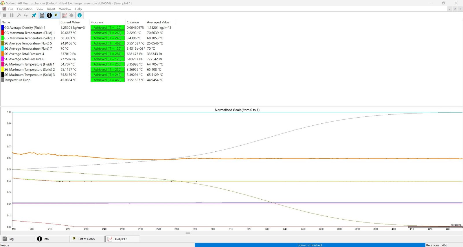
Confirm power dissipation, applied temperatures, environmental exposure, operating sequence and the component or system limits that govern acceptance.
Connect conduction, contacts, insulation, convection and radiation so the model explains where heat enters, travels and leaves.
Use steady, transient, thermal structural or CFD methods according to whether equilibrium, time history, deformation or fluid behaviour controls the decision.
Challenge convection, emissivity, contact conductance, material data and operating conditions where uncertainty can change the temperature conclusion.
Interpret hot spots, gradients, warm-up time, cooling performance and thermal movement against limits and practical design options.
Representative applications
Representative applications showing how the thermal route changes with the heat source, cooling mechanism, operating sequence and functional temperature limit.
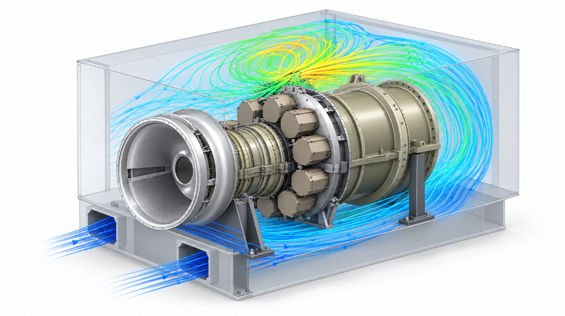
A Fabrixon engineering case study showing how CFD and thermal analysis traced compressor casing distortion to nonuniform enclosure cooling and differential thermal growth.
View case study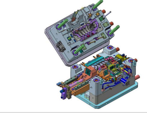
Production injection mould engineering for a thick wall PA6+GF30 component using selective conformal cooling, balanced filling and Moldflow led warpage control.
View case study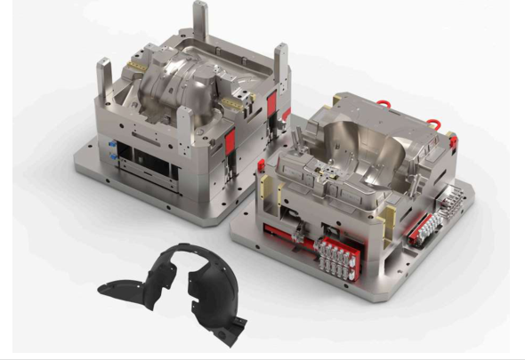
Large scale injection mould engineering for matched automotive exterior panels with zoned cooling, controlled filling, ejection and mould base structural validation.
View case studyThermal analysis reporting
Temperature values are useful only when another engineer can trace the heat sources, contacts, materials, convection, radiation, fluid conditions and initial state that produced them. The heat balance, sensitive assumptions and limitations remain visible.
Power dissipation, applied temperatures, ambient or fluid conditions, initial state, duty cycle and acceptance limits are recorded before the results are interpreted.
Material properties, interface resistance, convection, radiation, mesh controls and uncertain boundaries are documented with sensitivity evidence where they can change the conclusion.
Hot spots, gradients, warm-up time, cooling performance and thermally driven movement are translated into a design recommendation without overstating certification or temperature guarantees.
Typical deliverables
The package is defined around the thermal question, heat sources, material and contact data, boundary conditions, operating duty and next design action so temperature evidence, assumptions and revisions remain connected.
Thermal basis · heat loads · boundary conditions · temperature evidence · design actions · controlled report
Revision-controlled record of the thermal question, model basis, heat loads, boundaries, methods, results, limitations, conclusions and recommendations.
Temperature fields, heat flux, thermal gradients, maximum and minimum values and the locations or operating conditions governing the decision.
Heat generation, applied temperatures, ambient and fluid conditions, convection, radiation, insulation, initial state and open assumptions.
Thermal conductivity, heat capacity, density, emissivity, contact conductance, temperature dependence and references relevant to the assessment.
Baseline and revised temperatures, heat-path interpretation and recommended material, geometry, insulation, ventilation or cooling changes.
Agreed native solver files, result extracts, temperature histories, animations or review images where included in the work package.
Analysis workflow
A four-stage workflow keeps the temperature question, heat-path basis, model assumptions and next design action visible throughout the assessment.
Confirm the operating states, heat sources, environmental conditions, temperature or cooling target and the engineering decision the analysis must support.
Prepare geometry, materials, contacts, insulation, convection, radiation, fluid conditions and initial state with the model fidelity matched to the decision.
Run the selected steady, transient, thermal structural or CFD route, then test uncertain boundaries and confirm heat balance and result sensitivity.
Issue controlled temperature evidence, limitations and the material, geometry, insulation, ventilation or cooling changes that reduce thermal risk.
Buyer questions
Direct answers to the technical and commercial questions that usually determine whether a thermal assessment can be defined correctly.
Thermal analysis predicts temperature, heat flow and thermal gradients from defined heat sources, materials, contacts and environmental conditions. Depending on the problem, it can show maximum and minimum temperatures, hot spots, heat flux, warm up or cool down time, cooling performance and the temperature field used for thermal stress or deformation assessment. The result remains an engineering prediction based on the model inputs and assumptions.
Steady state analysis calculates the temperature field after time dependent heat storage effects have become negligible under a continuing operating condition. Transient analysis calculates how temperature changes with time during start up, shutdown, duty changes, heating, cooling or thermal cycling. The choice depends on whether the final equilibrium condition or the path and timing of the temperature response controls the design decision.
Useful inputs include CAD or drawings, material definitions, heat generation or applied temperatures, ambient and surrounding conditions, contact and insulation details, airflow or coolant data, operating sequence, initial temperature, target temperature limits and any available test measurements. Fabrixon identifies missing information and proposes sensitivity cases where convection, contact resistance or other boundary conditions remain uncertain.
Thermal CFD is appropriate when fluid flow controls cooling, heating or temperature distribution. Conjugate heat transfer is used when heat conduction within solids and heat transfer through the surrounding fluid must be solved together. Examples include ventilated enclosures, heat sinks, ducts, cooling passages, process equipment and heat exchangers. A solid thermal model is usually more efficient when the fluid effect can be represented reliably through known temperatures or heat transfer coefficients.
Yes. A steady or transient temperature field can be transferred into a structural model to predict thermal expansion, differential growth, distortion, contact changes and thermal stress. The structural result also depends on supports, joints, assembly sequence, reference temperature and material expansion data, so those inputs are defined separately from the heat transfer model.
Convection is defined from measured data, supplier information, recognised correlations or a CFD result, depending on the available evidence and the importance of the boundary. Radiation requires emissivity, surrounding temperatures and geometry or view relationships where it contributes materially. Thermal contact conductance or resistance is defined from interface condition, pressure, material and available test or reference data. Sensitivity studies are used when uncertain values can change the decision.
Cost and duration depend on geometry quality, number of materials and contacts, heat source definition, steady or transient scope, need for radiation or thermal CFD, thermal structural coupling, sensitivity studies, design iterations and reporting depth. A defined solid conduction study can be scoped quickly, while a ventilated enclosure, heat exchanger or transient coupled model requires more input preparation and solution time. The programme and commercial basis are confirmed after the initial engineering review.
START WITH THE THERMAL QUESTION
Share the model, material data, heat sources, operating conditions, cooling arrangement and the temperature limit that matters. Fabrixon will define the analysis route, expose the assumptions controlling the result and return evidence for the next design decision.