
IndustrialCompressorThermal Distortion
How CFD and thermal analysis were used to trace reduced running clearance risk to nonuniform enclosure cooling and differential casing growth.
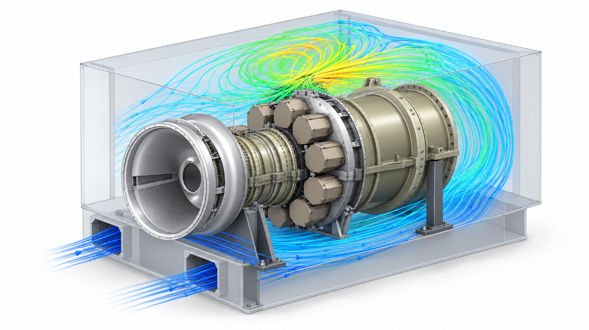
Finding the cause of clearance loss
The compressor showed recurring failure behaviour consistent with local blade to casing interaction. The investigation focused on whether the surrounding cooling arrangement was creating an uneven thermal field around the casing.
Determine whether enclosure airflow reached the casing uniformly around its circumference.
Establish whether recirculation could create persistent hotter and cooler casing regions.
Assess whether differential growth was relevant to the small running clearance at the front stage.
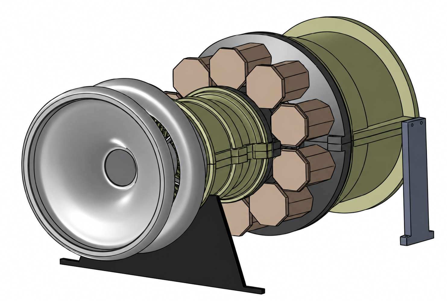
CFD and thermal assessment
The study combined geometry interpretation, enclosure airflow analysis and thermal response review. The objective was to understand whether the cooling pattern could distort the casing in a region where running clearance was limited.
Define the system
Review the compressor assembly and enclosure arrangement to identify the casing regions most affected by external cooling.
Assess airflow
Use CFD results to examine inlet flow, recirculation and cooling distribution around the compressor casing.
Relate heat to growth
Connect the resulting temperature field to differential casing expansion and running clearance risk.
Airflow confirmed uneven cooling
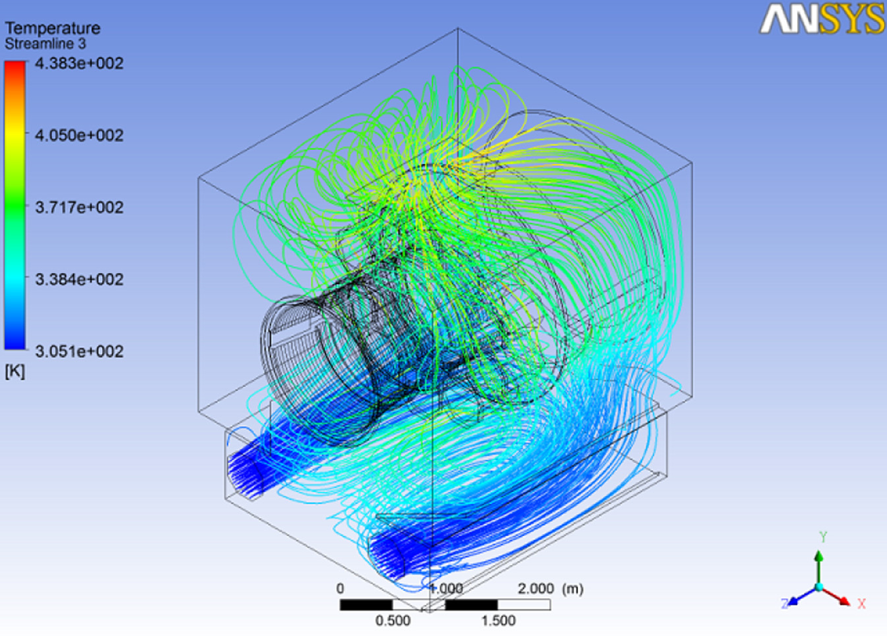
The CFD results showed that cooling air did not move uniformly around the compressor casing. Recirculation developed in the upper enclosure while cooler inlet air remained concentrated lower down and closer to the entry path.
The upper flow field formed a persistent recirculating pattern rather than a uniform sweep around the casing.
Different casing regions were exposed to different cooling conditions, creating the basis for a circumferential temperature gradient.
Thermal gradient changed casing growth
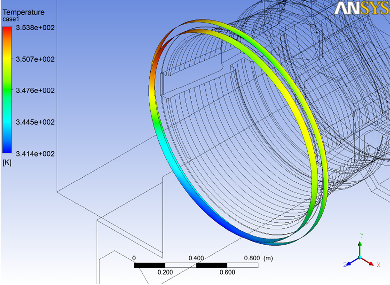
The front casing did not behave as a uniformly heated circular section. The upper and lower regions experienced different thermal conditions, so expansion differed around the circumference.
The significant result was the circumferential gradient rather than the highest temperature in the model.
Differential expansion changed the local casing shape in a region where only a small mechanical clearance was available.
The airflow pattern created a nonuniform circumferential thermal field. That produced differential casing growth and a credible path to local running clearance reduction at the front stage.
Clear direction for corrective engineering
The study connected external cooling behaviour to mechanical clearance risk and identified cooling distribution as the area requiring attention. This moved the investigation from recurring symptoms to a defensible engineering mechanism.
Nonuniform enclosure cooling produced a circumferential thermal gradient around the casing.
Improve cooling uniformity around the clearance sensitive casing region rather than treating temperature level alone as the issue.
Confirm any revised cooling arrangement through follow up simulation or measurement before drawing conclusions about long term performance.