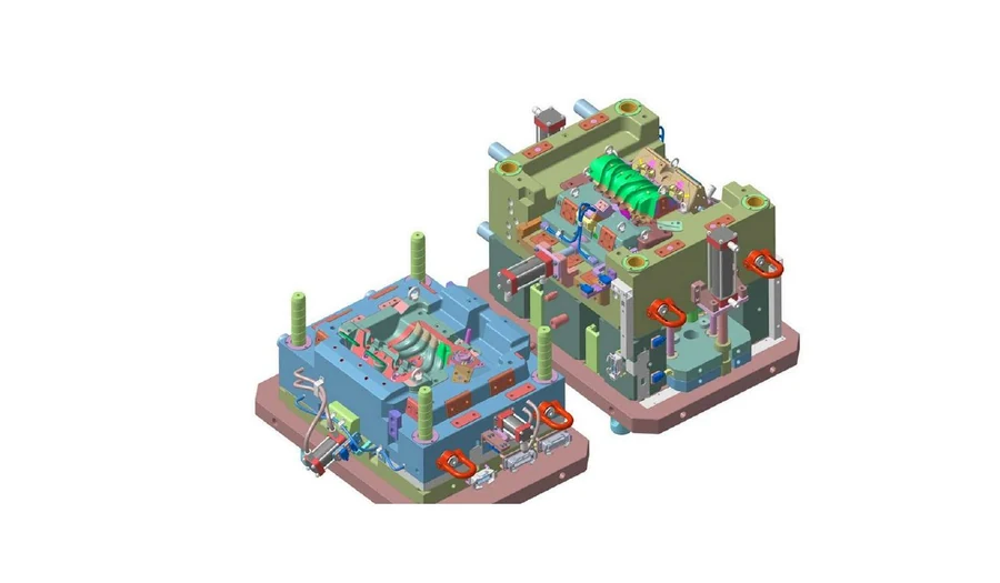
Plastic part DFM
Wall thickness, draft, ribs, bosses, undercuts, shutoffs, shrinkage, appearance zones, gate options and ejection feasibility reviewed against the selected material and production intent.

For OEMs, tool makers and plastics manufacturers
Plastic part DFM, injection mould design, mould flow analysis and controlled tool documentation developed as one connected engineering package.
Fabrixon at a glance
Specialist mould engineering supported by broader mechanical design capability, controlled documentation and experience across product and industrial programmes.
Talk to an EngineerMould engineering scope
We structure the programme around mouldability, production volume, tool architecture, process behaviour and the information your tool maker needs before steel is committed.
Wall thickness, draft, ribs, bosses, undercuts, shutoffs, shrinkage, appearance zones, gate options and ejection feasibility reviewed against the selected material and production intent.
Cavity count, parting strategy, gates, runners, slides, lifters, ejection, cooling, mould base and machine interfaces developed as one coordinated tool concept.
Fill, pack, cooling and warpage studies applied where they add decision value, with findings fed back into gate, runner, cooling and part geometry decisions.
Controlled cavity, core, insert, slide, lifter, ejection, cooling, venting and standard component geometry developed around the agreed tool maker and manufacturing route.
Native CAD, component drawings, BOMs, steel and finish requirements, exchange files, simulation evidence and revision records issued through agreed review gates.
Ways to work
Engage Fabrixon for a complete part and tool programme, recurring specialist capacity, or a defined mould engineering package inside an existing programme.
Plastic part engineering, DFM, mould architecture, detailed tool design, defined simulation studies and controlled documentation delivered through one project structure.
Discuss a mould programmeRecurring specialist capacity for tool makers, moulders and product teams managing variants, design changes, drawing backlogs and multiple tooling programmes.
Discuss dedicated capacityDFM review, mould concept, cavity and core design, cooling, mould flow analysis, documentation or correction of an existing tool design.
Discuss a defined scopePart and tool applications
The engineering route is defined around part geometry, resin, production volume, tool life and moulding process rather than applying one generic mould architecture.
Housings, covers, handles and visible components where appearance, texture, parting conditions and assembly interfaces shape the tool.
Functional enclosures, brackets, guards and machinery components requiring controlled geometry, material performance and repeatable assembly.
Interior, exterior and technical plastic parts developed around customer surface, dimensional, material and documentation requirements.
High volume components where cavity count, runner balance, cooling, repeatability and cycle objectives are commercially important.
Balanced multi cavity or family tools plus interchangeable insert strategies where common frame economics and variant flexibility matter.
Parts using inserts, multiple materials, slides, lifters or coordinated tool actions requiring integrated part, process and tooling decisions.
Advanced mould engineering
Where geometry, cycle performance, maintenance or programme economics justify more than a conventional tool arrangement, specialist features are developed as part of the mould architecture.
Thermal performance
Cooling passages following cavity geometry where conventional drilling cannot provide the required thermal control, applied where dimensional stability or cycle performance justifies the added complexity.
Complex tool motion
Slides, lifters, latch systems and hydraulic or pneumatic core pulls coordinated around the required release sequence, movement clearance and ejection strategy.
Production architecture
Feed system, cavity, cooling and ejection architecture coordinated with selected hot runner and standard component suppliers for repeatable high volume production.
Selected engineering evidence
Examples showing how tool architecture, simulation and controlled design decisions are applied to production mould programmes and complex tooling mechanisms.
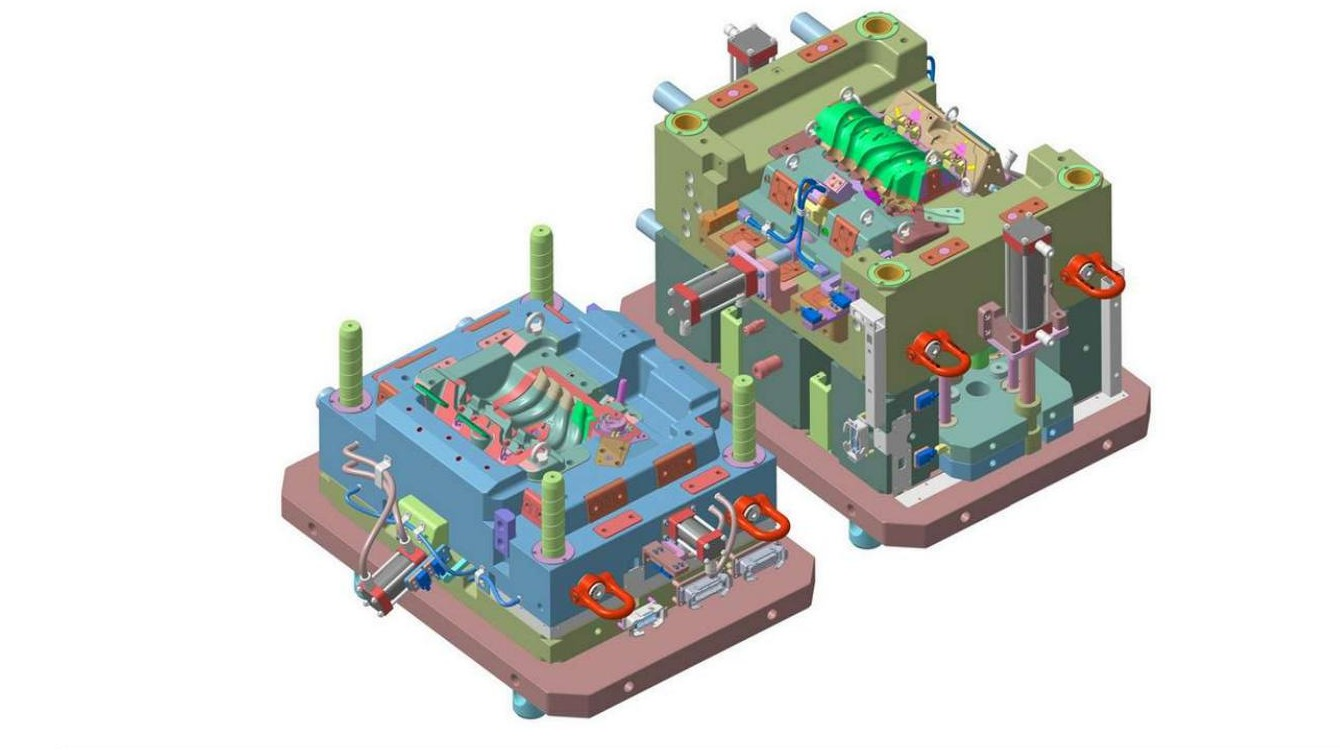
Production mould design using sequenced release mechanisms and CATIA motion verification to eliminate demoulding warpage.
View case study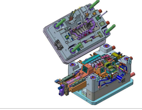
Production injection mould engineering for a thick wall PA6+GF30 component using selective conformal cooling, balanced filling and Moldflow led warpage control.
View case study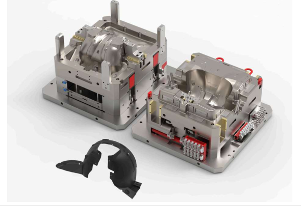
Large scale injection mould engineering for matched automotive exterior panels with zoned cooling, controlled filling, ejection and mould base structural validation.
View case studyWhy manufacturers outsource mould engineering
Outsourcing is most valuable when specialist tooling work, unresolved mouldability or programme peaks begin to delay quotations, tool release or production timing.
Access experienced mould design capability for cavity/core, slides, lifters, cooling, ejection and detailed documentation without recruiting for intermittent programme demand.
DFM findings, gate strategy, ejection, cooling and tool actions are coordinated rather than passed between separate part and tooling workstreams.
Flow, cooling and warpage studies can inform practical design choices while the part and tool architecture can still be changed economically.
CAD, drawings, BOMs, technical specifications, analysis evidence and revision records are consolidated into a controlled package for review and manufacture.
Engineering handover
Part intent, mould architecture, simulation evidence, tool documentation and revision status stay connected through the agreed review and release process.
 Moldflow
Native + neutral CAD · controlled tool drawings · simulation evidence · BOMs · tool maker files · revision status
Review findings, marked models, recommended geometry changes and the agreed mouldability basis for material, appearance and critical features.
Cavity, core, inserts, slides, lifters, ejection, cooling, runners, vents and selected standard components within the agreed design scope.
Assembly and component drawings covering interfaces, dimensions, tolerances, finishes, steel conditions and revision status.
Defined fill, pack, cooling or warpage results with assumptions, findings, limitations and recommended design actions.
Mould base, standard components, steel and hardness requirements, hot runner information and surface finish references where applicable.
Native CAD, STEP, DXF where required, controlled drawing register, review comments and the final issue package.
Buyer questions
Direct answers to the technical and commercial questions manufacturers ask before outsourcing plastic part and mould engineering.
Yes. Fabrixon can develop the plastic part and mould within one coordinated programme, or work from an existing part design. Scope can include DFM, part geometry, mould architecture, simulation and controlled tool documentation.
Yes. A standalone mouldability and DFM review can assess draft, wall thickness, ribs, bosses, undercuts, shutoffs, gate options, ejection and other features against the selected material and production requirements.
The most useful inputs are part CAD, drawings, resin, annual and lifetime volume, cavity count if known, cosmetic and critical dimensional requirements, target cycle time, moulding machine information, tool maker preferences and required timing.
Yes. The mould architecture can be developed around the nominated tool maker, mould base preferences, standard components, machining and EDM capability, hot runner supplier and moulding machine limits, with review points built into the programme.
The analysis route is selected around the design decision. Studies can compare filling pattern, pressure demand, weld lines, air traps, gate position, runner balance, cooling performance, shrinkage and warpage where the available data supports those questions.
Yes, where conformal cooling is technically and commercially justified. Cooling geometry can be developed around the cavity and assessed against thermal balance, dimensional stability and cycle performance objectives.
The handover is defined by scope and can include native mould assemblies, part and insert models, assembly and component drawings, BOMs, steel and hardness requirements, finish notes, STEP/DXF files, analysis reports and a revision controlled drawing register.
Timing depends on part complexity, cavity count, tool actions, hot runner integration, analysis scope, documentation depth and review cycles. Fabrixon confirms milestones, assumptions, timing and price in the written proposal before engineering begins.
Start with the engineering brief
Share what you are designing and the engineering support you need. Part CAD, drawings and production information can be added now or discussed after we review your enquiry.
Start with the essentials. Add a short note or files if they are available.