
Conformal CoolingProduction Mould
Production injection mould engineering for a thick wall PA6+GF30 component, combining selective conformal cooling, balanced filling and Moldflow led warpage control.
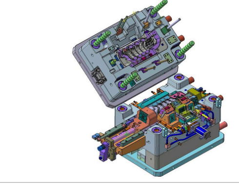
Client identity, proprietary part geometry, cooling channel dimensions, gate sizes and insert interfaces are withheld.
Client identity, proprietary part geometry, cooling channel dimensions, gate sizes and insert interfaces are withheld.
Reduce thermal imbalance before the tool is built
Thick sections can retain heat long after surrounding walls have frozen, while glass fibre reinforcement adds orientation dependent shrinkage. The mould therefore had to control thermal gradients, filling balance and release behaviour as one production problem.
Fabrixon developed the cavity and core package around controlled wall thickness, balanced gate placement and targeted cooling close to the highest mass regions rather than relying on longer cooling time alone.
Thick sections created uneven heat retention that had to be addressed at the geometry and cooling level.
PA6+GF30 made filling history and fibre orientation part of the dimensional control problem.
Gate position and flow direction were developed to move weld lines away from important regions.
Cooling had to follow complex high load areas while preserving tool strength, serviceability and a practical cycle.
Develop the geometry, flow path and cooling architecture together
Ribs, hollows and defined compensation regions maintained stiffness without simply adding local mass. Gate positions and flow direction were then developed to promote symmetrical filling and move weld lines away from critical functional areas.
Conventional drilled circuits were retained where practical, while conformal channels followed the cavity more closely in thermally demanding zones.
- Wall strategy
- Approximately ±10–15% target thickness variation around the controlled geometry.
- Filling
- Moldflow review of pressure, temperature, flow behaviour and fibre orientation.
- Cooling
- Conformal circuits concentrated near high mass regions and combined with conventional drilling.
- Thermal objective
- Approximately 5–10 °C overall differential with a ±5 °C zone uniformity requirement.
Use simulation to refine the production process before release
Moldflow analysis covered filling, temperature, fibre orientation and warpage. The results were used to refine both the gating strategy and the cooling arrangement before manufacturing release.
Specified production cycle range achieved.
Required operating temperature window achieved.
Thermal uniformity requirement achieved for warpage control.
Specified functional surface finish achieved.
Translate the validated mould concept into a controlled production package
The engineering package combined mould geometry, cooling and compensation layouts with manufacturing documentation in PDF, DWG and STEP formats. The recorded durability basis was 1.5–2 million shots, accounting for the abrasive PA6+GF30 material.
- Durability basis
- Tool architecture developed around the recorded 1.5–2 million shot service target.
- Handover
- Controlled technical documentation including cooling and compensation layouts.
- Process integration
- Wall thickness, gate location, fibre orientation and cooling treated as coupled variables.
Cooling close to the heat source controlled the real moulding risk
Increasing cooling time alone can hide thermal imbalance. Selective conformal cooling was used where straight drilling could not maintain a consistent relationship to the cavity surface, while Moldflow linked heat removal to filling and fibre orientation.
The completed mould met the required production duty
The successful project combined cavity geometry, gating, thermal management and process validation into one production tool. The specified cycle, mould temperature, zone uniformity and surface finish requirements were achieved without converting the public case study into unsupported higher performance claims.
- Production cycle
- Required 24–32 second duty achieved.
- Thermal control
- 60–80 °C mould range and ±5 °C zone requirement achieved.
- Surface requirement
- Ra 0.8–1.2 µm cavity finish achieved.
- Validation
- Moldflow used for filling balance, temperature, fibre orientation and warpage risk.