
Part & Manufacturing Drawings
Machined, formed and fabricated components documented from approved CAD, markups or established design intent with the manufacturing and inspection information required for the scope.

Engineering drawing & CAD drafting
Drawing production, revisions and CAD drafting support for manufacturers, OEMs and engineering teams. Fabrixon develops part, assembly, weldment and fabrication drawings, GD&T, controlled revisions and legacy CAD conversion within your standards, templates and approval workflow.
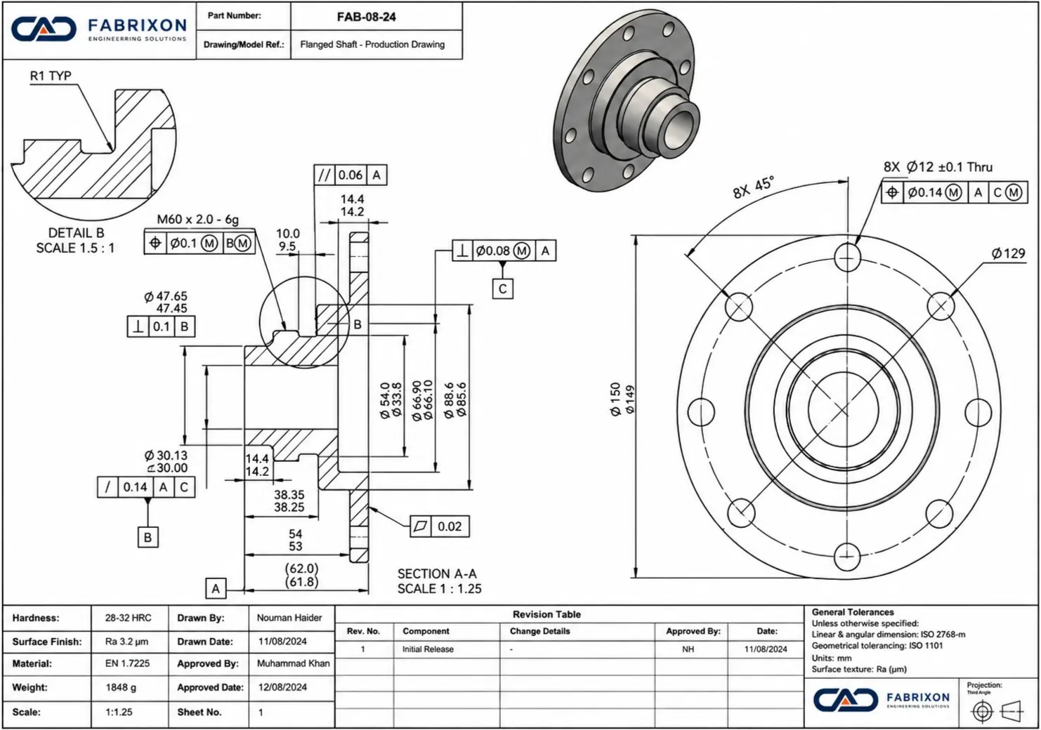
Machinery, manufactured products, drawing packages, validation and controlled technical documentation
Delivered across machinery, manufactured products, design packages and controlled engineering documentation scopes
Part, assembly, weldment, GD&T, revision control and legacy CAD conversion
Defined drawing packages, backlog sprints and reserved ongoing drawing support
Engineering drawing capabilities
From a defined drawing package to an accumulated backlog or recurring drawing office demand, the work is developed around the approved source, client standards, design authority, manufacturing information and release workflow.
Integrated drawing support
Fabrixon can take a defined drawing package, a backlog sprint or recurring weekly and monthly demand. Templates, title blocks, properties, numbering, revision practice and review responsibilities are aligned so external output behaves like part of your own drawing workflow.
Machined, formed and fabricated components documented from approved CAD, markups or established design intent with the manufacturing and inspection information required for the scope.
Equipment, stations and assemblies documented with views, sections, balloons, BOM structure, interface dimensions and installation references.
Welded frames and fabricated assemblies documented with member identification, weld information, cut lists, critical dimensions and fabrication notes.
Functional datums, feature controls, fits, limits and tolerance decisions developed where the drawing requires engineering interpretation for manufacture and inspection.
Controlled updates to models, drawings, BOMs, properties, registers and release information without losing revision status or source traceability.
Older drawings, scans, PDFs, DWG files and neutral geometry rebuilt into current CAD models and controlled documentation while preserving known design intent.
Common drawing workload problems
Manufacturers rarely lack drawing work. They lack dependable capacity to complete it without pulling experienced engineers away from design, problem solving and project decisions.
Models and design decisions exist, but the documentation queue cannot keep pace with manufacturing or supplier dates.
Experienced engineers are spending time creating views, updating notes, rebuilding BOMs and processing repetitive drawing changes.
Redlines, supplier comments and model changes are not being converted into controlled drawing revisions consistently.
Project releases, absence or urgent supplier needs create temporary demand that does not justify permanent recruitment.
Ways to work
A fixed drawing list, a delayed backlog and recurring drawing office demand should not be bought the same way. The support model is matched to the pattern of work and the level of engineering responsibility required.
A known set of part, assembly, weldment or fabrication drawings produced against agreed source information, standards and review points.
Fixed scope or estimated hoursReserved weekly or monthly capacity for drawing production, revisions, BOM updates, registers and documentation maintenance inside the client workflow.
Reserved recurring capacityA concentrated block of capacity to clear delayed drawings, accumulated redlines, legacy updates or a manufacturing release bottleneck.
Capacity block + priority listYour drawing system
External drawing support scales only when the output fits the engineering system already in use. During onboarding, Fabrixon captures the conventions that must stay consistent so recurring work can move without repeated explanation.
Sheet sizes, formats, zones, logos, approval fields, standard notes and title block properties are mapped before production begins.
ASME, ISO or client conventions, general tolerances, datum practice, feature control notation and preferred dimensioning rules are captured.
Part numbering, custom properties, descriptions, materials, quantities, item grouping and BOM structure are aligned to the client system.
Revision identifiers, change descriptions, review status, issue purpose, approval sequence and release conventions stay consistent with your workflow.
Approved symbols, weld notes, manufacturing notes, blocks, layers and reusable annotations are adopted to keep sheets consistent.
Folder structure, filenames, metadata, drawing registers and package structure are prepared for controlled PDM or document management handover.
Engineering approach
Drawing support works best when the output reflects the design basis, tolerancing decisions, manufacturing intent and release workflow already in use. Fabrixon aligns the source information, drawing rules and checking logic before production starts so the finished package can move cleanly into review, manufacture or supplier handover.
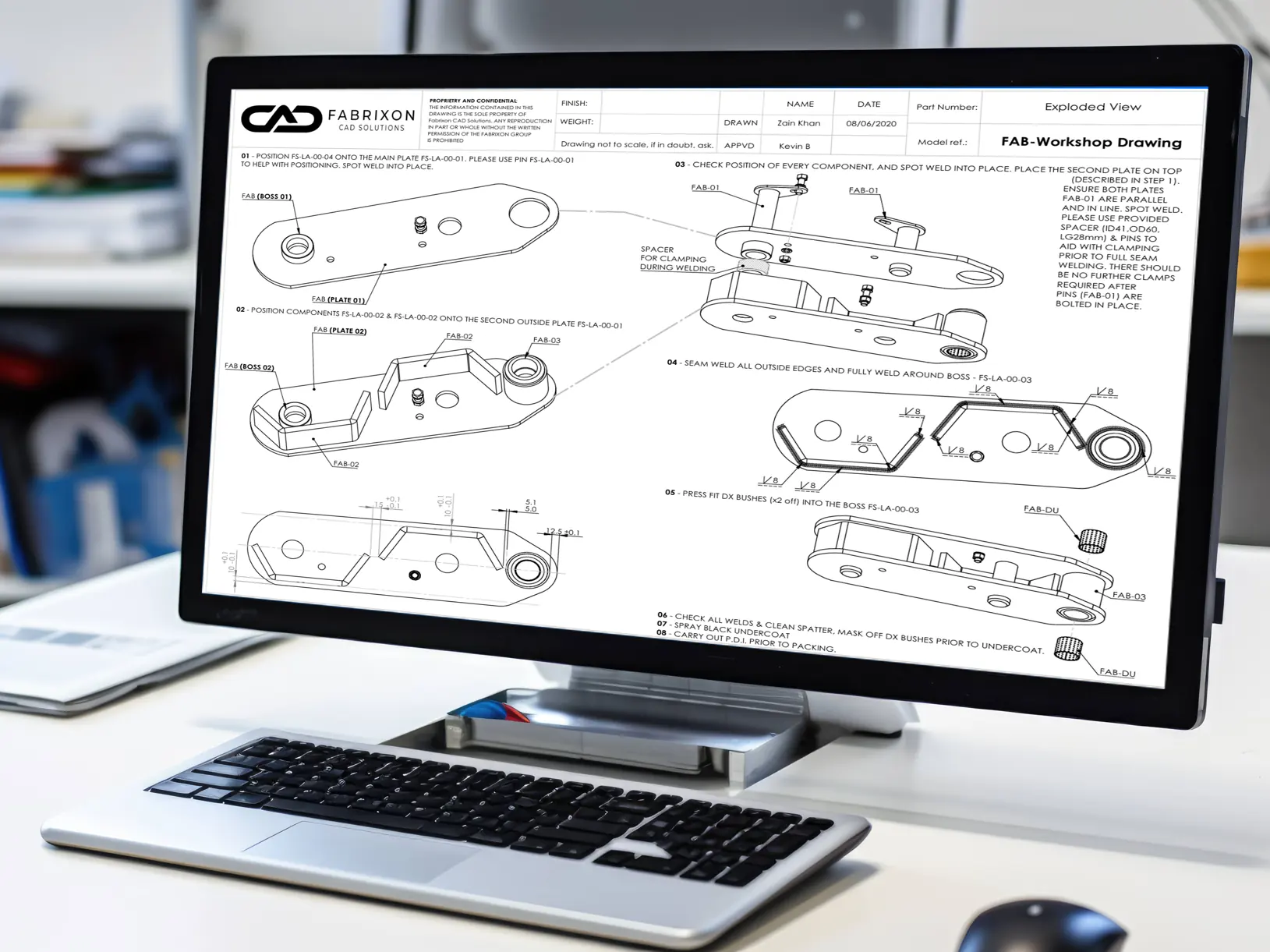
Confirm the governing model, source drawings, redlines, client templates, numbering rules, title block fields and applicable ASME, ISO or internal drawing standards before work begins.
Create the drawing set around the agreed part, assembly, weldment or fabrication scope so views, sections, sheets, item balloons and file relationships are structured consistently.
Dimensions, fits, datums, feature controls, notes, materials, finishes, weld information and BOM linked metadata are developed to suit the intended manufacturing and inspection use.
Views, properties, BOM data, revision status and drawing content are checked against the agreed source so released files remain technically aligned and traceable.
Native files, published PDFs, agreed exchange formats and revision information are handed back in a controlled set ready for review, supplier issue or continued drawing office support.
Selected drawing work
Explore engineering projects illustrating parametric CAD development, trailer design and manufacturing documentation.
Industrial product development case study showing how concept sketches and legacy 2D data were converted into controlled parametric 3D models, linked drawings and BOMs for faster engineering iteration and manufacturing documentation.
View case study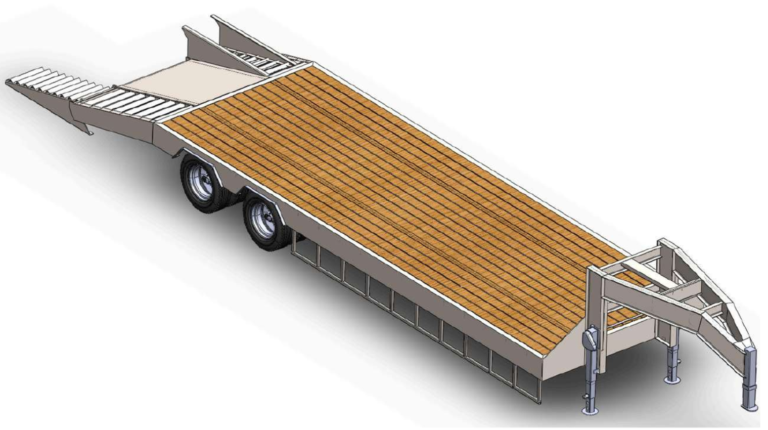
Parametric structural engineering of a 40 ton gooseneck lowbed trailer family with FEA led reinforcement, movement envelope checks and manufacturing documentation.
View case study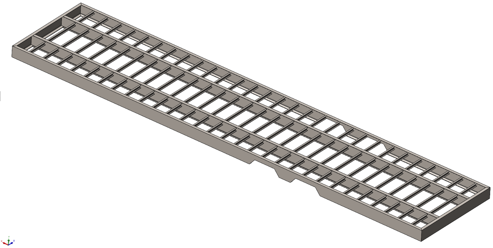
Structural design of a 40 ft gooseneck flatbed trailer chassis developed around a 30,000 lb GVWR, continuous load paths, local reinforcement and manufacturing documentation.
View case studyComplimentary drawing review
A representative drawing or small sample can be reviewed as a low risk first step. The review focuses on the issues most likely to create supplier questions, inspection ambiguity, revision confusion or repeated correction cycles.
Review of missing or ambiguous manufacturing information, view selection, critical dimensions, material and finish notes, interfaces and obvious inspection access issues.
Review of title block and annotation consistency, general tolerances, datum logic, obvious fit or feature control concerns and alignment with the agreed ASME, ISO or client practice.
Review of revision identifiers, change descriptions, source hierarchy, drawing to model consistency, BOM or register status and information needed for a controlled issue.
Typical deliverables
Outputs are agreed around the approved source, client standards and responsibility level so native files, published drawings, BOM information, revision status and supporting records remain aligned for engineering and supplier handover.
Native CAD · PDF · DWG · DXF · STEP · BOMs · revision registers
Controlled drawings with agreed views, dimensions, tolerances, datums, materials, finishes, manufacturing notes and inspection information.
Assembly views, sections, balloons, BOM structure, interface dimensions, exploded views and installation information where required.
Weld information, member identification, cut lists, materials, critical dimensions, fabrication notes and related assembly details.
Functional datum schemes, feature controls, fits, limits, general tolerances and supporting tolerance records where included in scope.
Item properties, descriptions, materials, quantities, cut list information, title block data and drawing linked records maintained with the package.
Updated native files, published outputs, change descriptions, drawing registers, issue status and agreed neutral format handover files.
How engagements work
A clear engagement path aligns the source information, client standards, responsibility level and drawing priorities before production starts, then keeps revisions and release status visible through handover.
Send models, drawings, redlines, templates and the current drawing list, package or backlog.
Agree source hierarchy, drawing conventions, responsibility, priorities, review level, required formats and the commercial support model.
Drawings and linked records move through the agreed queue, with missing information and engineering questions surfaced before controlled issue.
Native and published files, revision information and registers are returned, with the next priority or recurring drawing queue agreed where support continues.
Buyer questions
Direct answers to the operational, technical and commercial questions that determine whether external drawing support will work within an engineering team.
Fabrixon produces part and manufacturing drawings, assembly and general arrangement drawings, weldment and fabrication drawings, sheet metal drawings, GD&T and tolerance documentation, drawing revisions, BOM updates, drawing registers and legacy drawing conversions for machinery and manufactured products.
Yes. Fabrixon can create controlled 2D manufacturing drawings from approved 3D CAD models, markups, redlines or established design intent. The scope can include views, dimensions, tolerances, datums, GD&T, materials, finishes, manufacturing notes, BOMs and inspection information.
Yes. Older drawings, scanned sheets, PDFs, DWG files and neutral CAD files can be rebuilt into current drawings and usable 3D CAD models. Dimensions, tolerances, revision information and known design intent are reviewed during conversion so the new files remain traceable to the source.
Yes. Fabrixon supports defined drawing packages, drawing backlog sprints and recurring weekly or monthly drawing demand. Ongoing support can cover new drawings, revisions, redlines, BOM maintenance, drawing registers and documentation updates within the client workflow.
Fabrixon can work to agreed client standards and relevant ASME or ISO drawing conventions, including ASME Y14.5 and ISO 1101 where applicable. Common workflows include SolidWorks and AutoCAD, with native files and agreed outputs such as SLDDRW, SLDPRT, SLDASM, DWG, DXF, PDF, STEP and IGES.
Drawings are checked against the agreed source information, CAD model, client template, title block, properties, BOM, revision status and requested manufacturing information. GD&T, tolerance or design interpretation receives the agreed level of engineering review, and changes are returned with clear revision and issue status.
Turnaround depends on drawing complexity, source quality, standards, review requirements and the number of drawings. Target dates are agreed before work begins. Defined packages can use a fixed scope or estimated hours, backlog work can use a capacity block, and recurring demand can use reserved weekly or monthly capacity.
Start with the engineering question
Share a representative drawing, markup or drawing list. Fabrixon will review the standards, available source information and expected workload, then recommend a drawing package, backlog sprint or recurring capacity arrangement.