Machinery Frames & Equipment Skids
Fabricated bases and load-bearing frames developed around machinery loads, stiffness, equipment mounting, lifting, transport, access and installation requirements.

Industrial structural engineering
Design and validation of machinery frames, equipment skids, automation supports, access structures, heavy weldments and structural retrofits. Fabrixon develops each structure around the operating loads, stiffness requirements, equipment interfaces and intended manufacturing route.
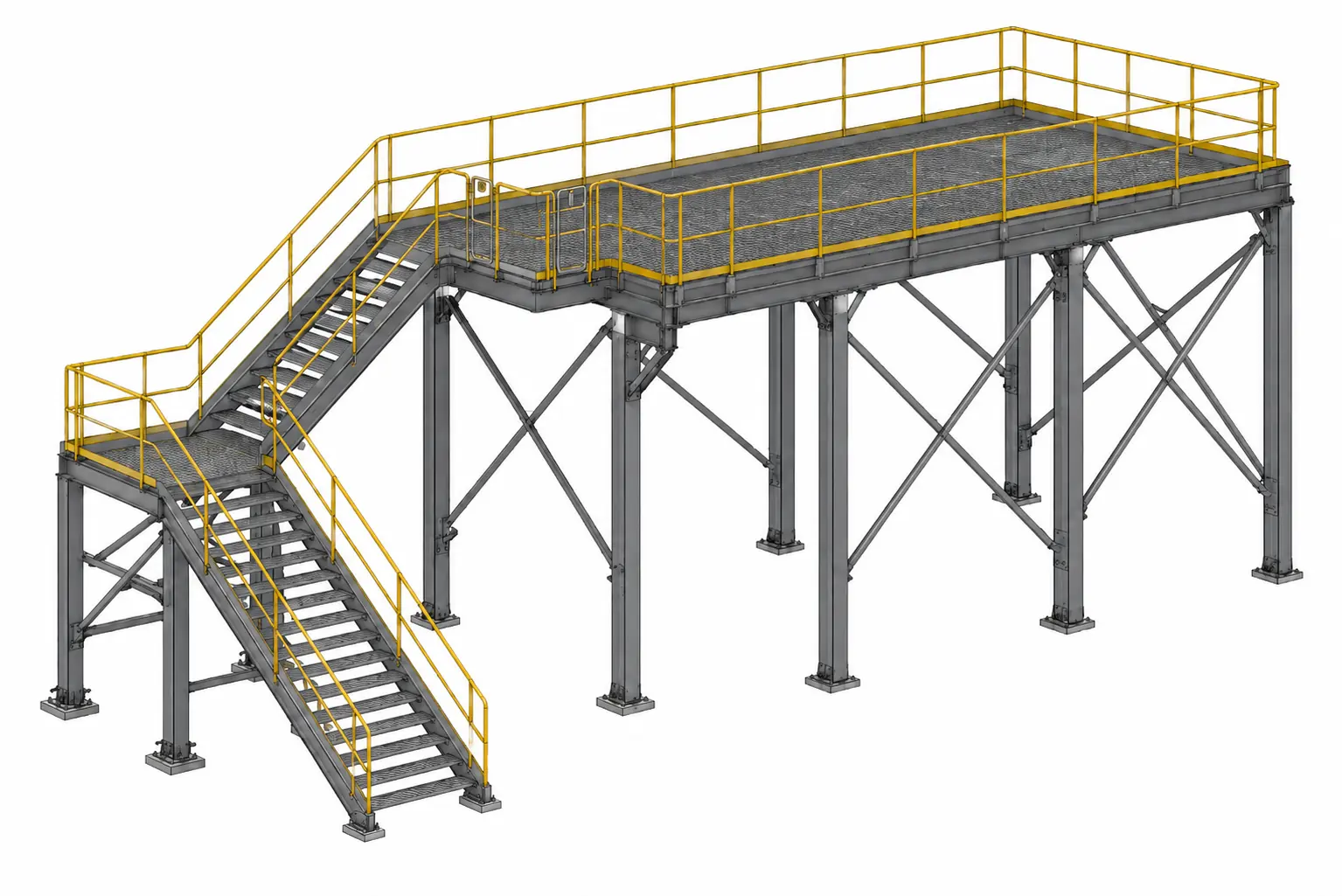
Machinery, structural steelwork, weldments, validation and manufacturing documentation
Structural frames, equipment supports, platforms and engineering programmes
Frames, skids, supports, platforms, heavy weldments and structural upgrades
From load definition through controlled structural engineering handover
Structural engineering capabilities
From a machinery base or equipment skid to an elevated handling structure or structural retrofit, the engineering is developed around real operating loads, stiffness, stability, interfaces, access and the intended fabrication and installation route.
Integrated structural engineering programme
Loads, restraints, structural architecture, member sizing, joints, interfaces and validation are developed around the same equipment duty. CAD, calculations, FEA where required, drawings, BOMs and revision information remain aligned as the structure develops.
Fabricated bases and load-bearing frames developed around machinery loads, stiffness, equipment mounting, lifting, transport, access and installation requirements.
Support steelwork for automated equipment, conveyors, lifts, towers and elevated machinery where structural movement can affect system performance.
Industrial platforms, support frames, crossovers and access steelwork integrated with equipment, maintenance routes, guarding boundaries and available space.
Load-bearing fabricated assemblies developed around force transfer, weld access, local reinforcement, distortion control, tolerances and assembly sequence.
Chassis, subframes and mobile structures developed around payload, coupling, suspension interfaces and agreed operating, transport and service load cases.
Assessment and redesign of installed equipment structures requiring reinforcement, revised interfaces, increased duty or controlled modification.
Common structural risks
Structural work becomes difficult when the real duty, restraint conditions, stiffness criteria, joints or existing condition are not converted into a defensible engineering basis before detailed design progresses.
Equipment mass may be known while process forces, acceleration, impact, transport, anchoring or credible load combinations remain uncertain.
Movement can affect machine alignment, tooling, robot accuracy, conveyor tracking, sealing, product transfer or fatigue performance.
Mounting points, base plates, guards, mechanisms, services, access and installation details can compete for the same space or load path.
Added equipment, increased throughput, revised operating loads, site modifications or damage concerns can make the remaining structural capacity uncertain.
Engineering approach
Useful structural engineering connects the real operating duty to the load path, stiffness, joints, validation evidence and manufacturing information rather than treating the steel model or FEA result as the final answer.
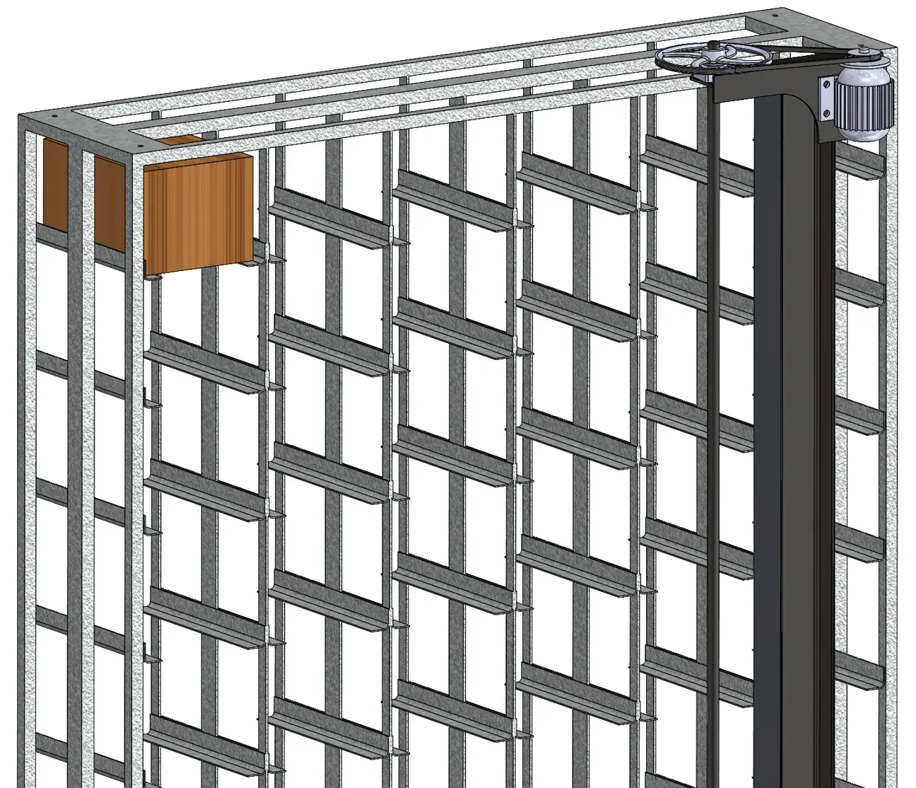
Equipment mass, process forces, acceleration, impact, maintenance, transport, lifting, support conditions, allowable movement and project-specific criteria.
Primary load paths, frame arrangement, sections, bracing, supports, base conditions, equipment interfaces, access and installation constraints.
Plates, sections, gussets, weldments, bolted joints, base plates, anchors, mounting points, tolerances and fabrication access.
Hand calculations, stiffness checks and FEA where geometry, local stress, deflection, buckling, fatigue or dynamic behaviour require deeper evidence.
CAD, drawings, BOMs, load definitions, calculations, validation reports, assumptions, revisions and supplier information issued as one controlled package.
Selected structural work
Selected structural engineering projects covering modular work platforms, industrial warehouse racking and trailer chassis design.
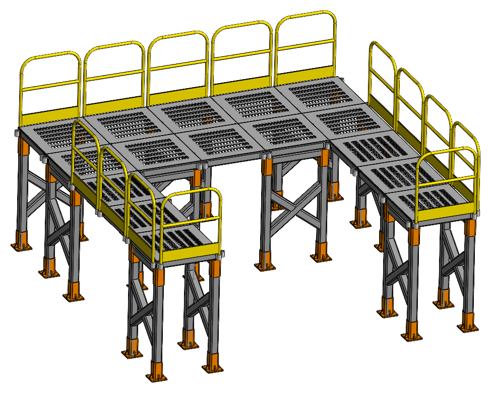
Modular elevated industrial work platform using repeated braced steel frames, panelised anti slip floor cassettes, bolted interfaces and perimeter guardrail modules.
View case study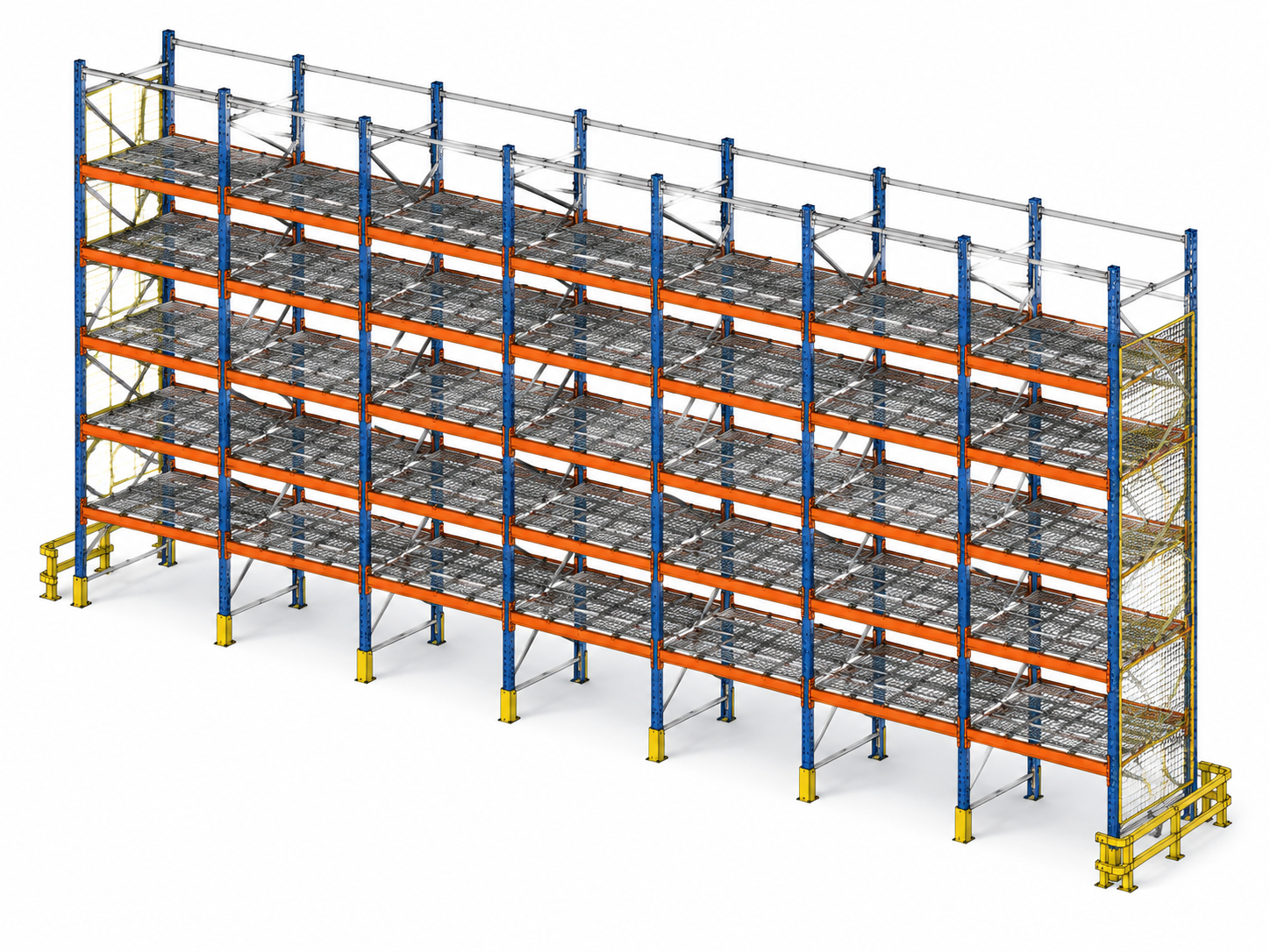
Structural design of a multi bay, multi level warehouse rack system with repeated load paths, braced upright frames, deck supports, anchored bases and rack end protection.
View case study
Structural design of a 40 ft gooseneck flatbed trailer chassis developed around a 30,000 lb GVWR, continuous load paths, local reinforcement and manufacturing documentation.
View case studySpecialist engineering review
Structural work is reviewed through the behaviour of the equipment and the fabrication route, not as an isolated steel model. The objective is to challenge the assumptions most likely to change the design decision.
Review of where loads originate, how they enter the structure, which supports and restraints are active, and which operating, transport or maintenance events should govern.
Review of critical members, local regions, joints, deflection, buckling, fatigue or vibration according to the agreed engineering question.
Review of weld access, tolerances, assembly route, mounting interfaces, assumptions, revision status and the documentation needed by suppliers and adjacent teams.
Typical deliverables
Outputs are agreed around the equipment duty, analysis depth and manufacturing route so structural models, calculations, validation evidence and fabrication information remain aligned for review and handover.
CAD · drawings · calculations · FEA · BOMs · revision control
Frames, skids, supports, platforms, weldments, chassis structures and agreed native or neutral CAD outputs.
Member, plate, weldment and assembly drawings with agreed dimensions, tolerances, joint information and revision status.
Structural sections, plates, material grades, manufactured items, purchased hardware and relevant supplier references.
Load definitions, assumptions, load combinations, member checks, joint checks and calculation records where included in the agreed scope.
Boundary conditions, mesh information, stress, deflection, buckling, fatigue or other agreed results with interpretation and recommendations where required.
Equipment mounting, support and anchor information, assumptions, open actions, change records and clarification notes for downstream teams.
How engagements work
A clear engagement path keeps the operating duty, load basis, interfaces, analysis depth and required outputs defined without turning the page into a process manual.
Send the equipment arrangement, CAD, drawings, photographs, known loads, calculations, site information or existing structural details.
Agree duty, loads, restraints, acceptance criteria, interfaces, assumptions, required analysis, outputs, review points and responsibilities.
Engineering progresses through defined technical reviews, with load path, stiffness, joint, FEA and fabrication issues raised as they surface.
Models, drawings, calculations, validation evidence, BOMs and agreed records are issued under revision control with supplier clarification support as scoped.
Useful starting inputs: equipment arrangement, component masses, operating forces, acceleration or impact data, support and restraint locations, allowable deflection, mounting interfaces, transport or lifting conditions, existing CAD or drawings and known project criteria.
Buyer questions
Direct answers to the technical and commercial questions that most often determine whether an industrial structural project can be scoped correctly.
The scope can include machinery frames, equipment skids, automation and conveyor support structures, platforms, heavy weldments, chassis structures, structural retrofits, load case definition, member and joint design, calculations, FEA, manufacturing drawings, BOMs and revision records. The exact package depends on the equipment, operating duty, available information and responsibilities agreed for the project.
Useful starting information includes the equipment arrangement, component masses, operating forces, acceleration, impact or vibration data, support and restraint locations, allowable deflection, mounting interfaces, access requirements, transport or lifting conditions, material preferences and any CAD models, drawings or photographs. Missing inputs are identified and recorded during the initial engineering review.
Load cases are developed from the real operating conditions, including self weight, equipment loads, process forces, acceleration, impact, maintenance, transport and other credible events. The calculation method, load combinations, allowable stress or factor of safety criteria and any project specific code requirements are agreed during scoping. Conservative assumptions are documented where confirmed data is not yet available.
Hand calculations are often appropriate for initial sizing, simple beams, columns, plates, bolts and clearly defined load paths. FEA becomes more useful where geometry, load transfer, joints, contact, local stress, deflection, buckling, fatigue or dynamic behaviour cannot be represented reliably with simple methods. Fabrixon selects the level of analysis needed for the design decision rather than applying FEA to every component by default.
Yes. Fabrixon can review available drawings, measurements, photographs, material information and revised load requirements to assess the affected members, joints and interfaces. The scope can include calculation or FEA review, reinforcement concepts, replacement details, updated drawings and controlled change records. Site verification and material confirmation requirements are identified during scoping.
Fabrixon provides structural design, calculations, FEA, drawings and engineering evidence within the agreed scope. Where a project or jurisdiction requires a registered, chartered or locally licensed engineer to stamp calculations, approve building interfaces or issue statutory certification, that responsibility must be assigned to an appropriately authorised professional or approval body.
Cost and duration depend on the quality of the starting information, number of load cases, structural complexity, existing condition work, calculation and FEA depth, drawing requirements, review cycles and project interfaces. A defined frame or retrofit may be shorter than a larger multi structure programme. Scope, assumptions, programme and commercial basis are confirmed in writing before work begins.
Start with the engineering question
Share your structure, load case or capacity concern. An engineer will review the available information, identify the critical loads, interfaces and missing inputs, and define the most practical engineering scope for your project.