Internal Flow in Ducts, Pipes & Manifolds
Velocity, pressure, separation and recirculation through connected passages, bends, junctions and plenums.

FLOW PERFORMANCE AND SYSTEM RESISTANCE
CFD for ducting, piping, manifolds, valves, process equipment and connected fluid systems. Fabrixon quantifies pressure drop, velocity distribution, branch balance, recirculation and operating range so geometry and equipment decisions can be made on a documented flow basis.
FLOW EVIDENCE FOR DESIGN DECISIONS
Defined boundaries. Interpreted flow. Clear design actions.

Mechanical design, fluid systems, simulation, industrial equipment and engineering review
Flow analysis and validation projects
across industrial equipment, manifolds,
process systems and fluid handling applications
Internal flow, pressure loss, distribution, restrictions, process flow and system interaction
From flow question and boundary definition through solution, sensitivity and design action
FLUID FLOW CFD CAPABILITIES
From a defined component pressure loss study to a connected manifold or process flow question, the CFD route is selected from the geometry, operating conditions, fluid behaviour and engineering decision.
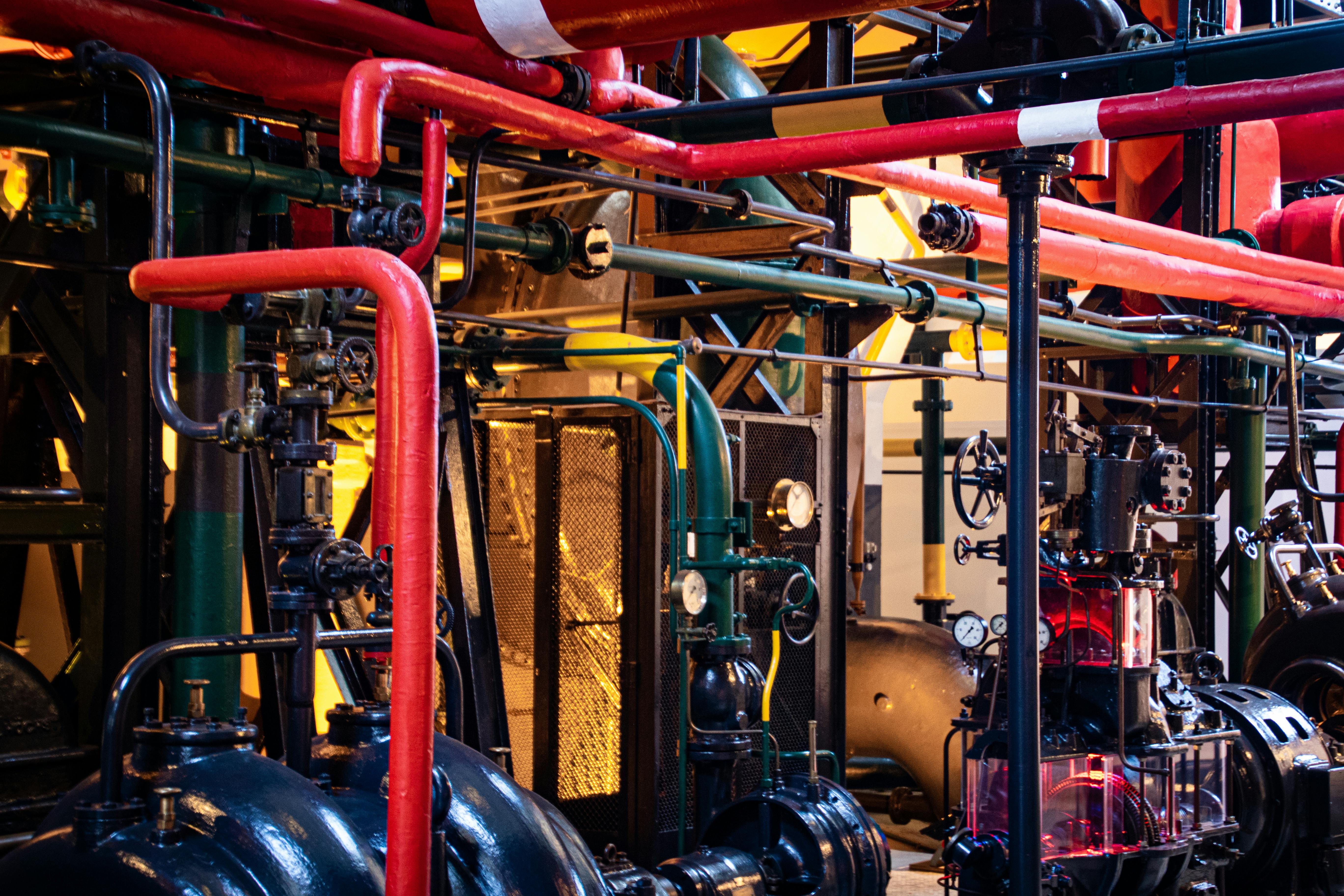
CONNECTED FLOW VALIDATION
Fluid properties, inlet and outlet conditions, system resistance, local restrictions and operating points remain connected throughout the assessment. Mesh refinement, turbulence treatment and additional physics are added only when they can materially change the engineering conclusion.
Velocity, pressure, separation and recirculation through connected passages, bends, junctions and plenums.
Pressure budget, local and distributed losses, recovery and available pump or fan margin across the operating range.
Branch balance, outlet uniformity, maldistribution and balancing concepts across parallel paths or process regions.
Component pressure loss, flow coefficient, jets, separation, recovery and local low pressure regions.
Internal circulation, dead zones, mixing behaviour, residence indicators and inlet or outlet arrangement.
Inlet quality, swirl, downstream resistance and connected system behaviour around fluid moving equipment.
Common flow performance risks
CFD becomes valuable when pressure loss, distribution or recirculation could reduce capacity, consume pump or fan margin, create inconsistent process conditions or force late geometry changes.
The connected system must achieve a target flow rate, but distributed resistance and local losses leave too little operating margin.
Branches, outlets, nozzles or cooling paths receive unequal flow, creating inconsistent process or equipment performance.
Separation, recirculation and abrupt geometry changes consume pump or fan head and can force larger equipment or higher energy use.
Flow rate, valve position, fluid properties or connected resistance can shift the system away from the condition used for the initial design.
Engineering approach
The simplest CFD model capable of resolving the engineering decision is preferred. Numerical complexity is added only where the governing flow behaviour requires it.
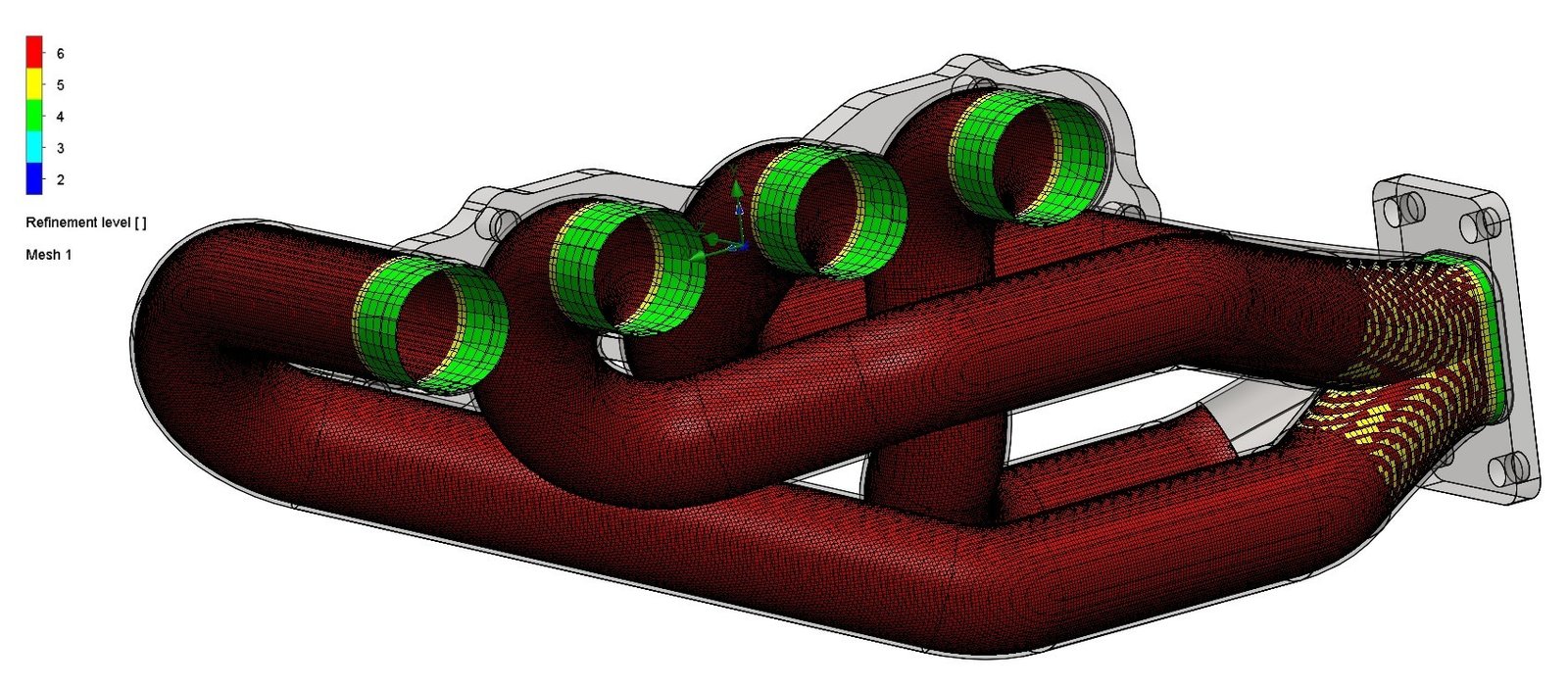
Required flow, available pressure, distribution target, operating range and acceptance criteria are agreed before the domain is prepared.
Inlet, outlet, pressure, flow and equipment conditions are based on the surrounding installation so the model remains physically compatible with real duty.
Geometry preparation, near wall treatment, turbulence, rotating zones and local refinement are selected around separation, swirl and the result quantity controlling the decision.
Convergence, mass balance, mesh sensitivity and applicable calculations, supplier data or measurements are checked before the result becomes a recommendation.
Pressure losses, distribution, recirculation and operating margin are converted into practical geometry, balancing or system changes.
Representative applications
The modelling route changes with the connected flow path, operating point, fluid behaviour and performance requirement. These examples show how the analysis is framed around the engineering decision.
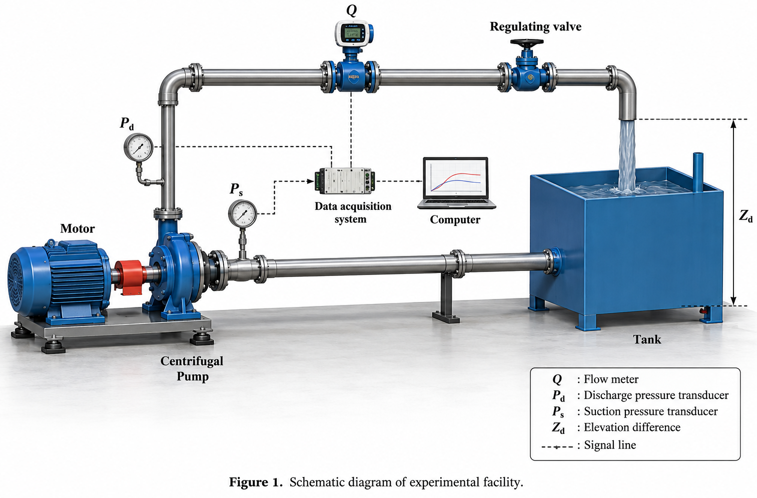
Case study showing how pump testing and 3D CFD were used to compare centrifugal pump impeller geometries, explain internal flow behaviour and improve pressure development.
View case study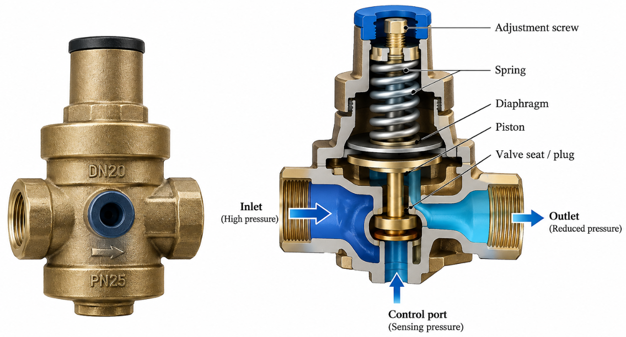
Case study showing how steady state CFD, force balance modelling and hydraulic testing were combined to predict pressure reducing valve behaviour and validate pressure regulation performance.
View case study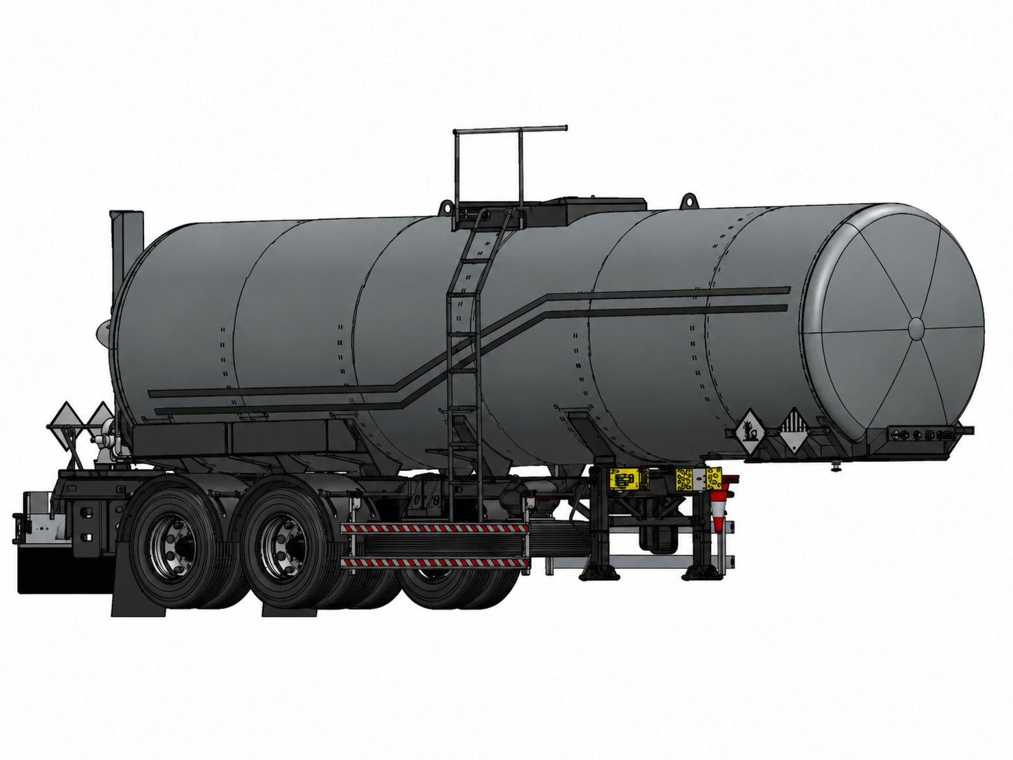
Integrated engineering of a 25,000 litre tanker vessel, tri axle chassis, CFD supported slosh control and pressure and discharge system packaging.
View case studyFLUID FLOW CFD REPORTING
Pressure and velocity results are useful only when another engineer can trace the geometry simplifications, fluid properties, operating points, boundary conditions, numerical models and solution checks that produced them.
Fluid properties, pressure and flow conditions, equipment data, valve positions, operating range, reference locations and acceptance criteria remain explicit.
Domain simplification, mesh controls, near wall treatment, turbulence or rotating models, residual behaviour, mass balance and sensitive inputs remain visible.
Restrictions, recirculation, branch imbalance, pressure recovery and operating margin are translated into geometry or system recommendations with limitations stated clearly.
Typical deliverables
The package is defined around the flow question, connected system, operating points, numerical model and next design action so pressure, velocity, boundary records and assumptions remain connected.
Revision controlled record of the flow question, geometry basis, fluid data, operating cases, numerical methods, results, limitations, conclusions and recommendations.
Pressure fields, velocity maps, streamlines, flow rates, branch balance, pressure loss and the locations or operating cases governing the decision.
Inlet and outlet conditions, operating points, fluid density and viscosity, temperature basis, wall conditions, roughness and open assumptions.
Geometry preparation, simplifications, mesh strategy, local refinement, near wall treatment, turbulence or rotating model, convergence and mass balance.
Baseline and revised pressure or distribution results, controlling flow features and recommended geometry, balancing or operating changes.
Agreed native solver files, controlled result exports, tables, review images and animations where they improve technical communication.
Analysis workflow
A four stage workflow keeps the pressure, flow or distribution question, connected system boundaries, numerical controls and next design action visible throughout the assessment.
Confirm the required flow, available pressure, distribution target, operating cases, fluid data and the engineering decision the study must support.
Prepare the flow domain, relevant geometry, fluid properties, inlet and outlet conditions, wall treatment and connected pump, fan or system data.
Establish the baseline field, confirm convergence and mass balance, test sensitive modelling choices and compare the required design or operating cases.
Issue controlled pressure and velocity evidence, limitations and the geometry, balancing or operating changes that improve flow performance.
Buyer questions
Direct answers to the technical and commercial questions that usually determine whether an internal flow assessment can be defined correctly.
Fluid flow CFD predicts how a defined fluid moves through a component or system. Depending on the question, it can estimate pressure drop, velocity distribution, flow rate, branch balance, recirculation, stagnation, jet behaviour and the effect of geometry or operating changes. The result remains an engineering prediction based on the geometry, boundary conditions, fluid data and numerical model.
Yes. CFD can estimate pressure loss across a component or connected flow path and show how total flow divides between branches, outlets or process regions. The model must include suitable reference locations, fluid properties and operating conditions. Hand calculations, supplier data or test results are used as cross checks where they are available and applicable.
Useful inputs include CAD or drawings, the fluid and its operating temperature, inlet and outlet conditions, expected flow rate or pressure range, wall roughness where relevant, valve or component positions, pump or fan data, and the performance question or acceptance criterion. Missing inputs can be identified during the initial engineering review.
Boundary conditions are derived from the connected system rather than chosen for convenience. They may use mass flow, volume flow, velocity, static pressure, total pressure, pump or fan data, symmetry or periodic conditions depending on the model. The combination must be physically compatible with the real system and is documented in the report.
The turbulence and near wall treatment are selected around the flow regime, separation risk, swirl, wall effects and required result. Mesh refinement is concentrated where velocity or pressure gradients control the conclusion. Numerical convergence, mass balance and result sensitivity are reviewed rather than relying on one default model or mesh size.
Yes, where the geometry, operating data and required level of detail are suitable. Fabrixon can assess manifolds, restrictions, valves, process vessels and the connected flow around pumps or fans. Specialist multiphase, cavitation or blade resolved rotating machinery analysis is confirmed separately because it requires additional data and modelling controls.
Cost and duration depend on geometry preparation, number of operating points, fluid behaviour, turbulence or rotating flow requirements, convergence difficulty, design comparisons and reporting depth. A focused component study may take several working days, while a multi case system assessment can require several weeks. Scope, programme and commercial basis are agreed after the initial review.
START WITH THE FLOW QUESTION
Share the model, fluid data, operating points, connected system information and the pressure, flow or distribution target that matters. Fabrixon will define the CFD route, expose the assumptions controlling the result and return evidence for the next design decision.