
Centrifugal PumpImpeller CFDOptimization
How physical pump testing and 3D CFD were used to compare impeller geometries, explain internal flow behaviour and improve pressure development while maintaining overall pump performance.
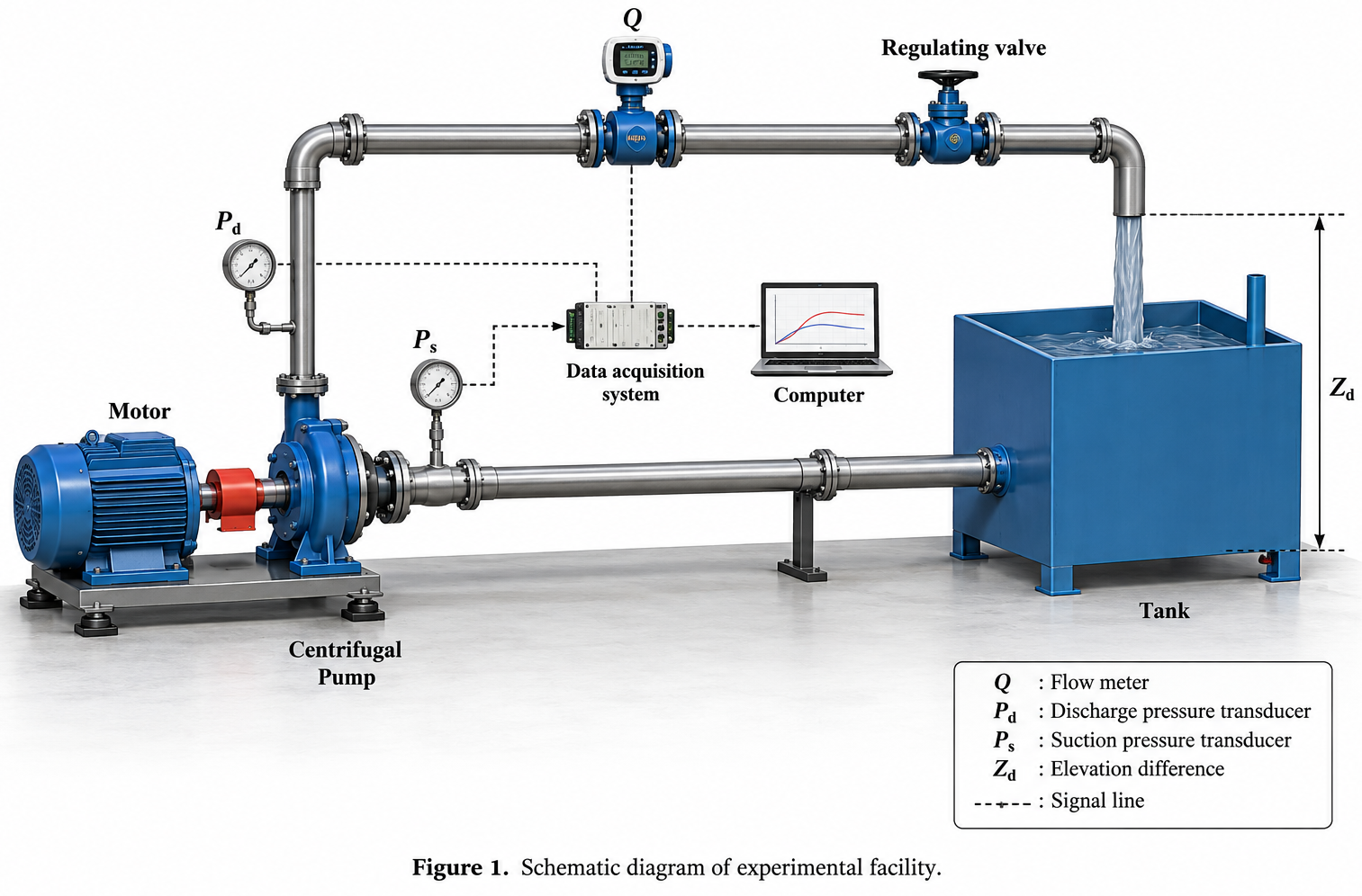
Increase pump head without sacrificing performance
The design problem was to increase pressure generation without simply trading away flow quality or overall pump performance. The investigation focused on whether a controlled change in impeller blade curvature could redirect the internal flow more effectively while keeping the comparison technically fair.
Determine whether revised blade curvature could produce a stronger pressure rise through the impeller and volute.
Check whether the geometry changed disturbed flow regions rather than only shifting the external pump curve.
Separate geometry effects from prototype material and manufacturing differences before accepting any design conclusion.
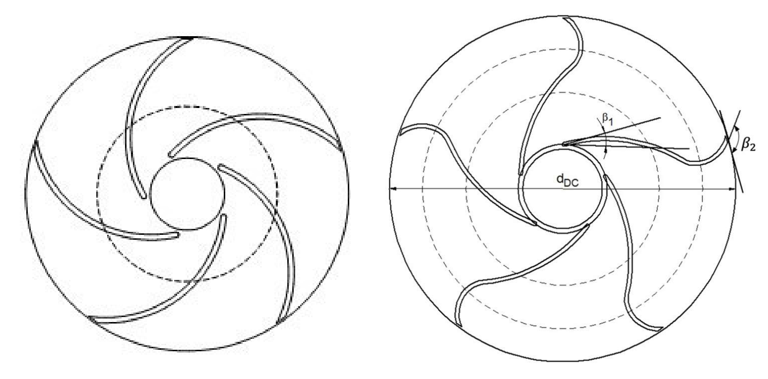
Combine physical testing with CFD interpretation
Alternative impeller geometries were evaluated experimentally before CFD was used to explain the internal mechanism behind the measured performance differences. The numerical model was then checked against measured pump characteristics so that flow field interpretation was tied back to physical evidence.
Create controlled impeller variants
Change the blade curvature strategy while retaining the core pump architecture and a like for like reference geometry.
Measure complete pump behaviour
Compare head, flow and overall performance across the operating range rather than relying on a single design point.
Use CFD to explain the difference
Resolve pressure and velocity fields through the impeller and volute, then compare simulated characteristic curves with physical measurements.
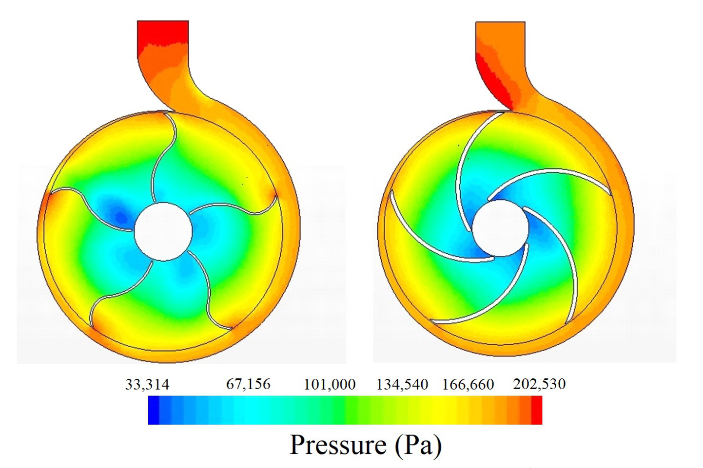
Pressure development explained the performance gain
The CFD results showed pressure increasing from the impeller eye toward the blade tips for both geometries. The selected double curvature design developed a stronger pressure front through the volute and discharge region, providing a credible fluid dynamic explanation for the higher measured pump head.
The revised geometry produced stronger pressure development through the outer impeller and volute region.
Changing the blade path altered how momentum was transferred into the volute, linking geometry directly to the measured head improvement.
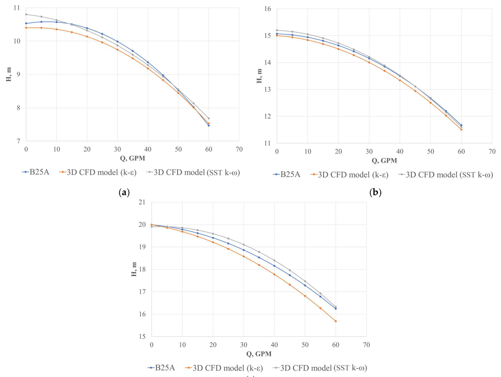
Pump testing confirmed the CFD performance trend
Measured pump characteristics were compared directly with the CFD predictions across representative operating conditions. The simulated and experimental curves followed the same trend closely, providing sufficient confidence to use the numerical model for interpreting internal pressure and flow behaviour.
Measured and simulated head flow behaviour remained closely aligned across the tested operating range.
Agreement at the system level supported use of the CFD model to explain the internal flow mechanism behind the design improvement.
The performance gain was not simply a material or manufacturing effect. The revised blade path changed how the fluid was driven toward the volute, creating a stronger pressure front and a credible mechanism for the measured increase in pump head.
Validated direction for impeller redesign
Physical testing and CFD converged on a revised impeller geometry that improved head generation and extended the useful flow range without an unacceptable overall performance penalty. The analysis provided both a measured result and an explanation of why the geometry worked.
Blade curvature and transition position were confirmed as meaningful design variables for improving centrifugal pump performance.
The selected geometry produced a clear head improvement and increased the attainable flow range across the tested conditions.
Measured and simulated characteristic curves showed close agreement, supporting further geometry development using the CFD model.