Modal & Natural Frequency Analysis
Natural frequencies, mode shapes, mode coverage and mass participation under defined mounting conditions, including prestress where it materially changes the modes.

MODAL AND VIBRATION ANALYSIS
Modal and vibration analysis for machinery, conveyors, equipment frames and mechanical assemblies exposed to operating excitation, transport vibration or shock. Fabrixon connects natural frequencies, support conditions, damping and excitation sources so the dynamic assessment supports a clear engineering decision.
DYNAMIC PERFORMANCE BEFORE RELEASE
Natural frequencies. Excitation mapping. Response evidence. Clear design actions.
Mechanical design, structural behaviour, machinery dynamics and engineering validation
Dynamic analysis and design validation projects across machinery and industrial equipment
Modal, harmonic, resonance, random vibration, transient response and design mitigation
From excitation and mounting definition through response, sensitivity and design action
Modal & vibration capabilities
From resonance screening to forced response under operating, transport or shock inputs, the analysis route is selected from the excitation type, response quantity, frequency range, damping evidence and the engineering decision that must be resolved.
Modal & vibration capabilities
Mass, stiffness, supports, damping and excitation remain connected throughout the assessment. Modal analysis establishes the vibration characteristics; harmonic, random or transient response is added when amplitude, acceleration or dynamic stress must be quantified.
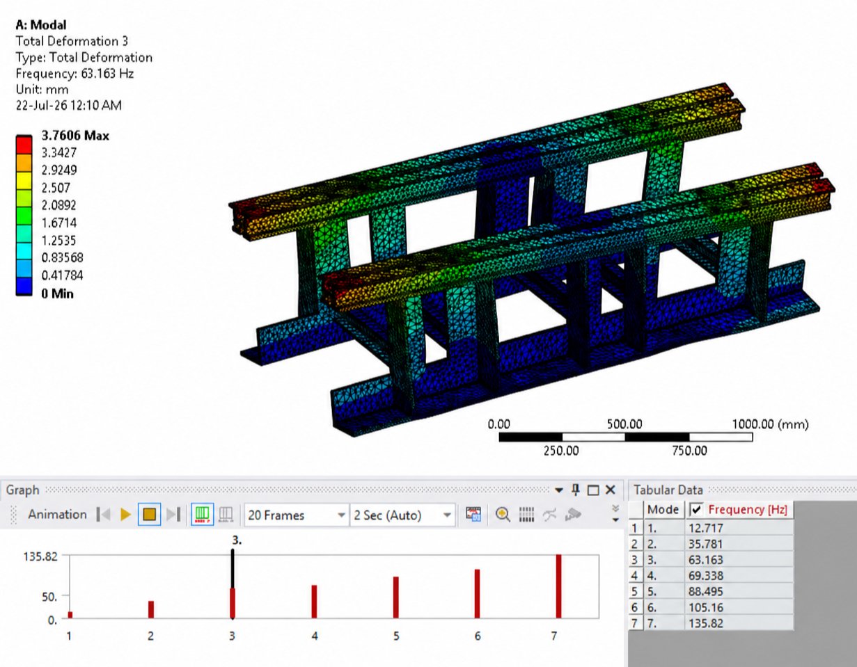
Natural frequencies, mode shapes, mode coverage and mass participation under defined mounting conditions, including prestress where it materially changes the modes.
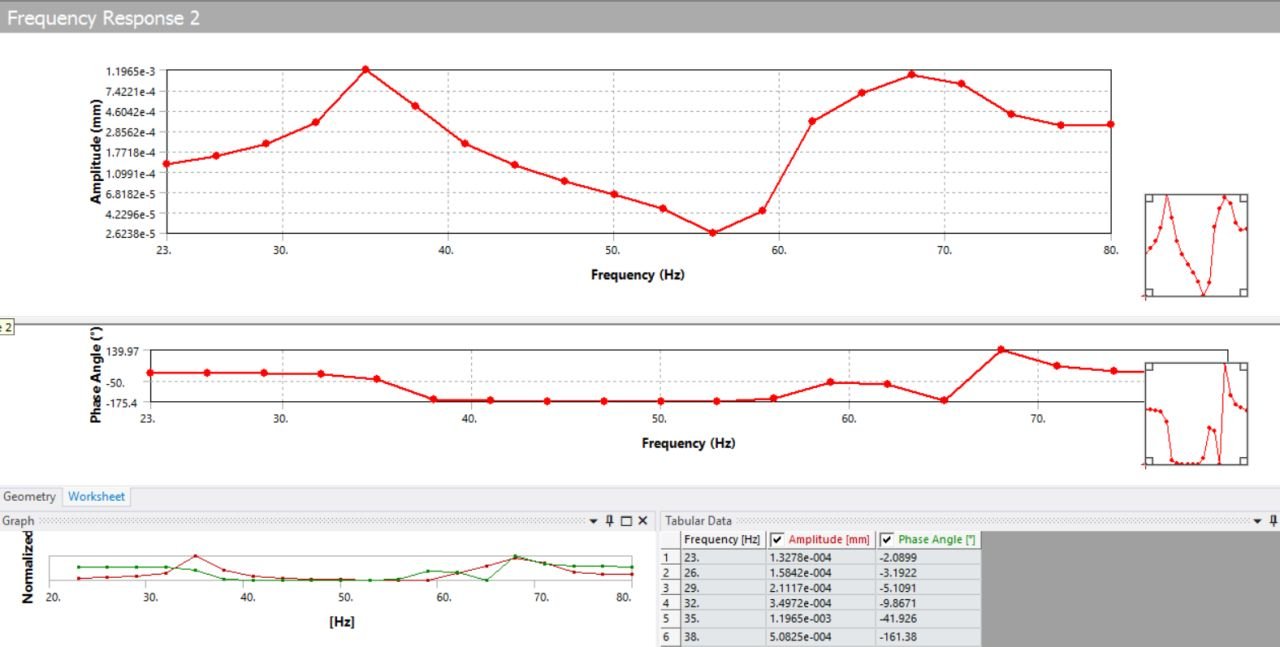
Steady state displacement, velocity, acceleration or dynamic stress across a defined frequency range under sinusoidal force or base excitation.
Operating speeds, harmonics, orders and process frequencies mapped against structural modes to identify frequency separation and resonance risk.
Statistical response under broadband excitation defined by a power spectral density, including RMS response and statistical peak assumptions where applicable.
Time domain response to impact, shock, start and stop events or another arbitrary time varying input where sequence and event timing control the result.
Controlled comparison of stiffness, mass, supports, isolation, damping or operating changes using one dynamic basis so the response improvement is clear.
Common dynamic risks
Dynamic analysis becomes valuable when operating frequencies, flexible structures, transport inputs or shock events create a question that static stress alone cannot resolve.
A motor, conveyor, fan, pump or repeated process input can align with a natural frequency inside the intended operating range.
Measured vibration may show a dominant frequency without revealing the governing mode shape, excitation source, support condition or load path.
Alignment, sensor stability, product handling, cyclic stress or process quality can be governed by vibration even when static strength is acceptable.
Transport vibration, shock, impact, start and stop events or variable process loads cannot be represented by one steady forcing frequency.
Engineering approach
A dynamic result is useful only when supports, mass distribution, joint behaviour and the frequency range represent the real assembly closely enough to support the decision. Response complexity is added only when it can change the engineering conclusion.
Operating speeds, harmonics, process inputs, transport spectra, shock events and the response limit are agreed before the analysis route is selected.
Geometry, attached masses, joints, support compliance, contact and prestress are included where they can change relevant modes or response.
Natural frequencies, mode shapes, participation and coverage are resolved and compared with the expected operating frequency map.
Harmonic, random or transient inputs are applied where required, with damping and support uncertainties tested when they materially affect the result.
Critical modes, response peaks and sensitive interfaces are converted into stiffness, mass, mounting, isolation, damping or operating recommendations.
Representative applications
The analysis route changes with the excitation source, response quantity and operating environment. These application areas show how different dynamic questions are framed before the model is built.
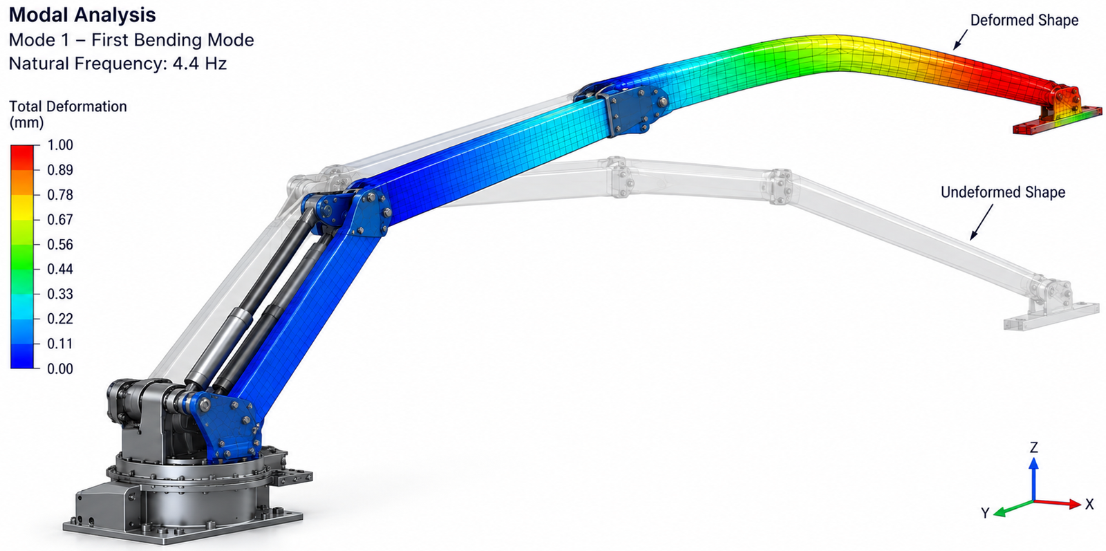
A Fabrixon engineering case study showing how modal FEA, harmonic response analysis and physical testing were used to understand vibration risk in a long reach mobile robotic arm.
View case study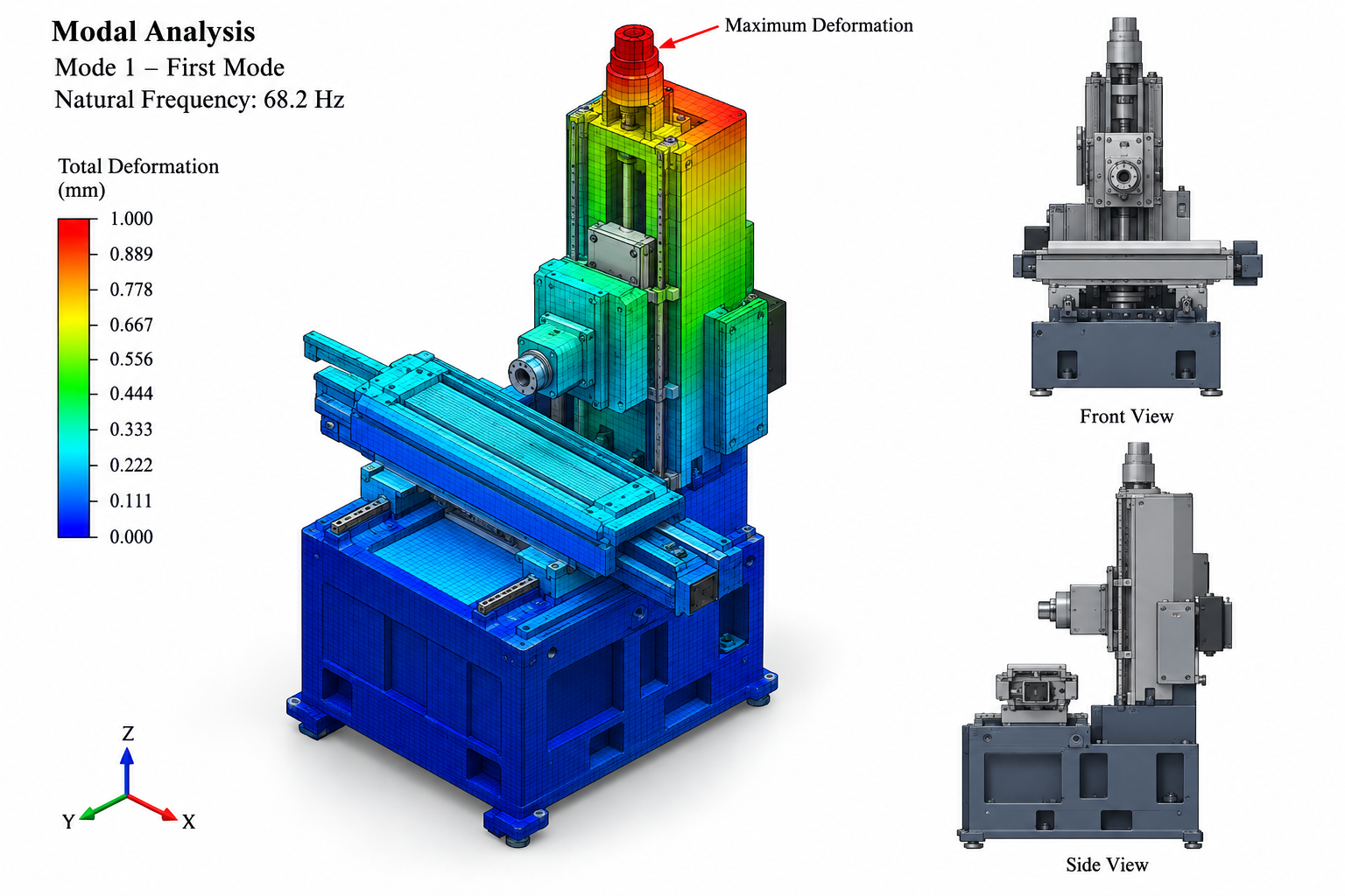
Case study showing how modal FEA, physical impact testing and topology guided structural redesign were used to improve resonance margin in a high precision grinding machine.
View case study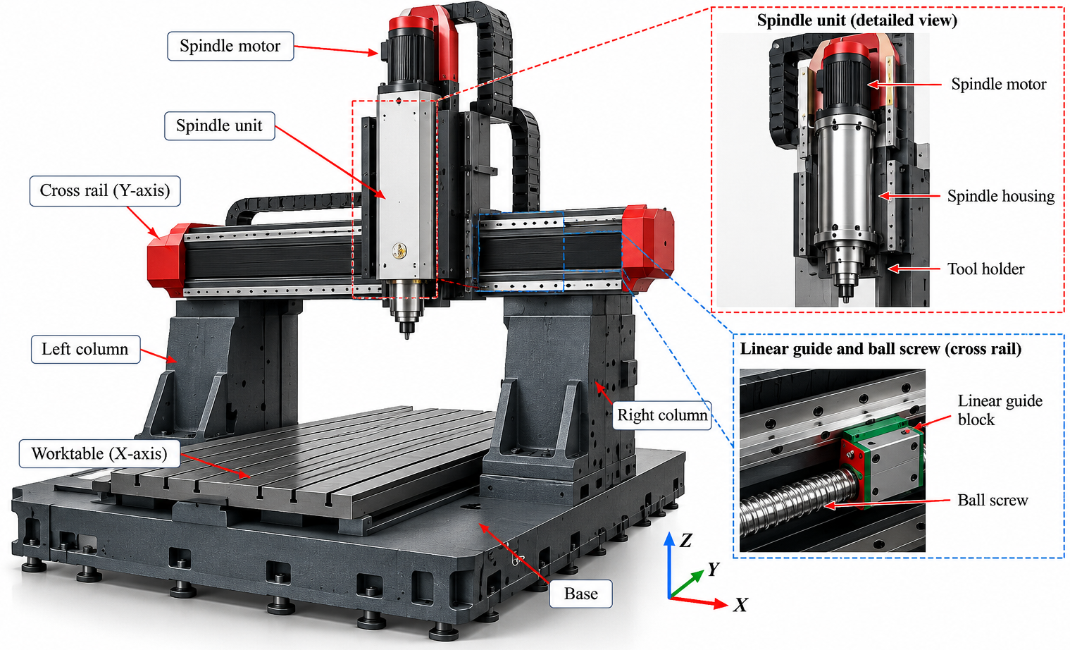
Case study showing how structural FEA, physical stiffness testing and optimization were combined to identify flexible machine regions and guide a lighter, better supported redesign.
View case studyDynamic analysis reporting
Natural frequencies and response values are meaningful only when another engineer can follow the geometry, mass, supports, joints, excitation, damping and frequency range that produced them. Sensitivity, limitations and the governing design action remain visible.
Geometry simplification, attached masses, mounting compliance, joints, contact, prestress where relevant, mesh controls and extracted frequency range are recorded before modes are interpreted.
Operating orders, force or base inputs, PSDs, time histories, damping values, phase assumptions and required displacement, velocity, acceleration or stress outputs remain connected.
Frequency separation, governing deformation patterns and response locations are translated into a design or operating decision without presenting the report as product certification.
Typical deliverables
The package is defined around the dynamic question, mass and stiffness basis, mounting conditions, excitation input, damping assumptions and next design action so modes, response evidence, assumptions and revisions remain connected.
Model basis · modes · excitation · damping · response · mitigation · controlled report
Revision controlled record of the model basis, analysis route, excitation, damping, results, limitations, conclusions and recommendations.
Frequency table, mode shape visualisations, mode coverage, participation data and the modes that matter to the operating question.
Operating frequencies, harmonics, force or base input, PSD or time history, damping values, source references and open assumptions requiring confirmation.
Frequency response functions, RMS or time history results, peak frequencies, response quantities and the structural locations governing the conclusion.
Baseline and revised modes or response, decision table and recommended stiffness, mass, support, damping, isolation or operating changes.
Agreed native solver files, result extracts, frequency tables, animations or review images where included in the work package.
Analysis workflow
A four stage workflow keeps the dynamic question, mounting basis, excitation, damping, response and next engineering action visible throughout the assessment.
Confirm the equipment, operating range, excitation source, required response quantity, acceptance criterion and design decision.
Prepare or review mass, stiffness, supports, joints, attached equipment, contact and damping assumptions that can change the relevant behaviour.
Extract modes, map excitation and apply harmonic, random or transient response where required, including sensitivity to decision critical assumptions.
Issue controlled frequency and response evidence, limitations and recommended stiffness, mass, support, isolation, damping or operating changes.
Buyer questions
Direct answers to the technical and commercial questions that usually determine whether a dynamic assessment can be defined correctly.
Modal analysis calculates the natural frequencies and corresponding mode shapes of a component, structure or machine under the defined mass, stiffness and support conditions. It identifies how the structure tends to deform at each mode and provides the basis for resonance screening and downstream harmonic, random or transient response analysis.
Modal analysis alone does not predict the operating vibration amplitude because it does not include the full forcing magnitude, damping and response calculation. Harmonic response, random vibration or transient dynamic analysis is added when the excitation input is available and the design decision depends on displacement, velocity, acceleration or dynamic stress.
Useful inputs include a 3D model or drawings, material data, component masses and inertias, support and mounting conditions, joint or isolator information, operating speeds, forcing frequencies, measured vibration data, PSD inputs or time histories, damping information and the response limit or design question. Fabrixon identifies missing inputs and proposes sensitivity cases where necessary.
Resonance risk is assessed by comparing relevant natural frequencies and mode shapes with the operating excitation range and its harmonics or orders. Frequency separation is reviewed first, then a forced response analysis is used where response magnitude, damping or a narrow separation margin could change the decision.
Harmonic response predicts the steady state response to sinusoidal excitation over a frequency range. Random vibration uses a power spectral density input to estimate statistical response under broadband excitation. Transient dynamic analysis calculates the time history response to shock, impact, start and stop events or another arbitrary time varying load.
Supports, joints, contact, distributed mass and mounting compliance are represented to match the real assembly as closely as the available data allows. Damping is taken from test data, manufacturer information or an appropriate reference where available. When damping or support stiffness is uncertain and materially affects the conclusion, sensitivity cases are reported.
Cost and duration depend on model quality, assembly size, contact and joint complexity, required frequency range, number of excitation cases, damping uncertainty, availability of measured or specified inputs, redesign iterations and reporting depth. A modal screening study can be scoped quickly, while random vibration or transient response with uncertain inputs normally requires staged definition. The programme and commercial basis are confirmed after the initial engineering review.
START WITH THE DYNAMIC QUESTION
Share the model, support conditions, operating speeds, excitation input or measured vibration data and the response question that must be resolved. Fabrixon will review the starting evidence, identify the missing inputs and define the modal or vibration assessment needed for the next engineering decision.