
Long Reach RoboticArm VibrationAnalysis
How modal FEA, harmonic response analysis and physical testing were used to identify resonance sensitive regions and improve confidence in a mobile robotic arm model.
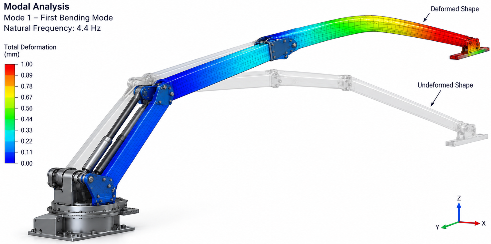
Vibration risk in a mobile long reach arm
The robotic arm was intended to work from a moving ground platform rather than a rigid factory foundation. Terrain induced motion therefore entered the structure through the base, while the long reach and lightweight upper assembly made end effector vibration a practical concern for positioning, sensing and structural reliability.
Understand how motion from the mobile platform could excite structural modes through the robot base.
Compare representative arm positions because reach, centre of mass and stiffness changed with configuration.
Identify structural motion that could reduce positioning accuracy and sensor performance at the working end.
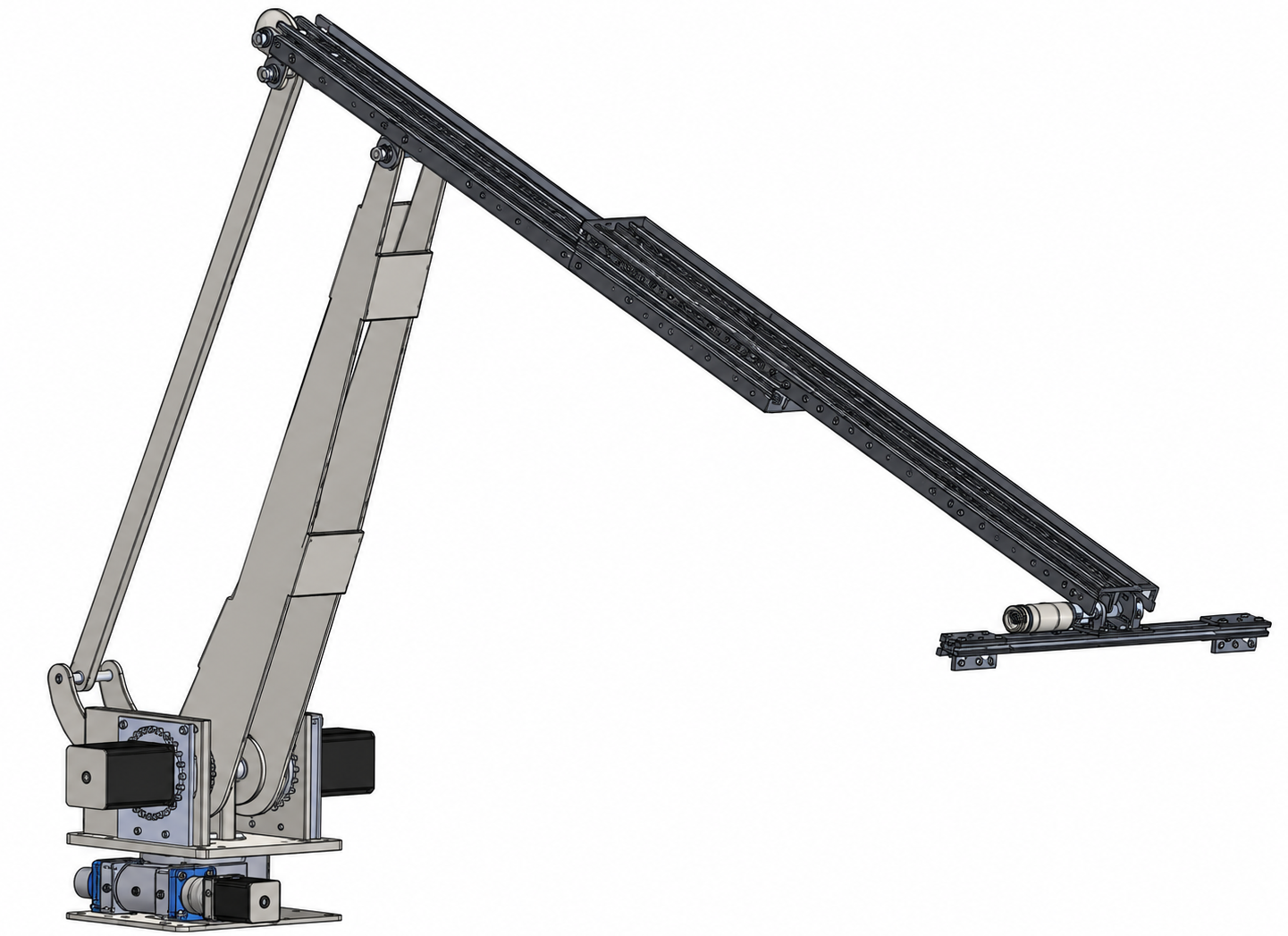
Simulation and physical testing
The study combined simplified structural modelling, modal analysis, harmonic response assessment and physical impact testing. More than one working pose was considered, and the numerical model was revisited when laboratory measurements exposed behaviour that the original idealised support condition did not fully capture.
Represent the dynamic structure
Simplify nonessential geometry while preserving the mass and stiffness distribution needed for modal behaviour, then assess representative working poses.
Identify modes and forced response
Extract natural frequencies and mode shapes, then evaluate how base motion can amplify vibration near structurally sensitive frequencies.
Use test data to refine the model
Compare physical impact test results with FEA and revise support or connection assumptions where the measured system behaves differently.
Low modes exposed upper arm flexibility
The first structural modes were dominated by vertical and lateral movement of the long upper section. Higher modes introduced torsional and bending behaviour, while changing the arm configuration altered stiffness distribution and the modal response. A base excitation sweep then showed that end effector motion could rise sharply when the input approached these modes.
The slender upper structure carried most of the dominant deformation in the lower structural modes.
The extended configuration was more sensitive to base induced vibration because the structure became less dynamically stiff.
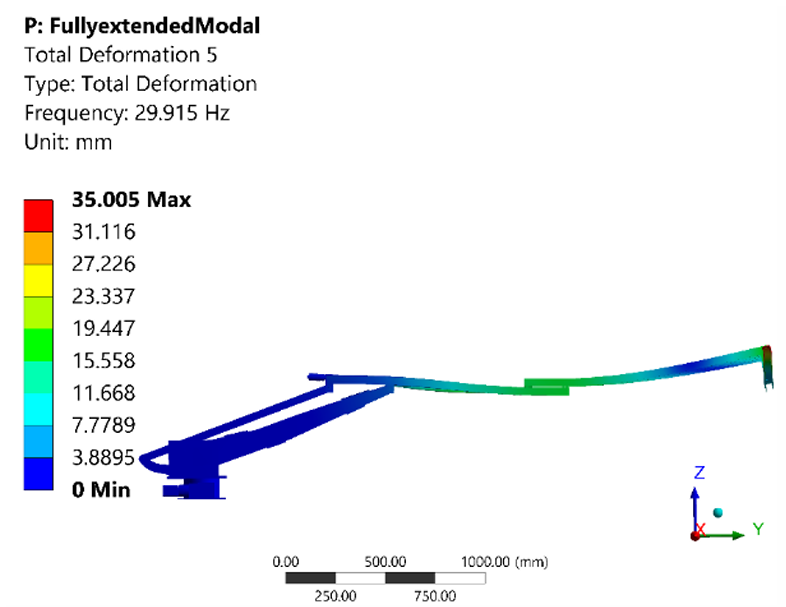
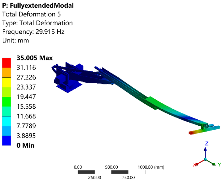
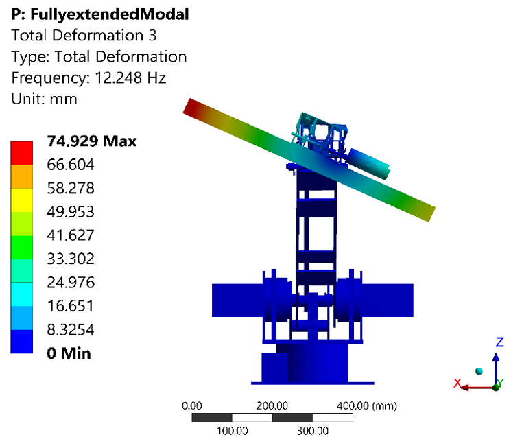
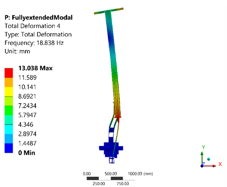
Selected modal FEA results showing how deformation patterns change across the arm structure and vibration modes.
Testing exposed support flexibility
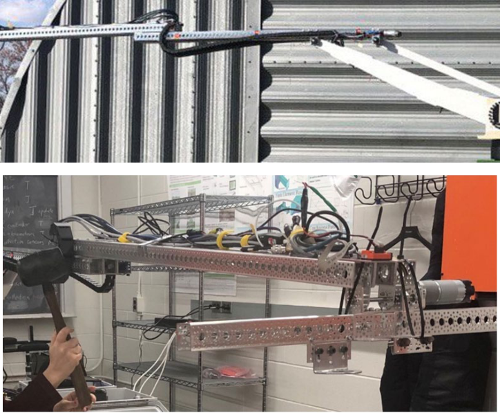
Impact testing was used to compare measured resonances with the FEA model. The main mode family correlated well, but additional low frequency behaviour appeared in the physical system because the laboratory mounting and connections were not perfectly rigid.
Support and connection behaviour were revised so the numerical model better represented the physical mounting condition.
The corrected model reproduced the measured modal behaviour closely, with reported differences remaining within approximately ten percent.
The extended upper arm was the dominant low frequency flexible region, and base excitation could strongly amplify end effector motion near resonance. Physical testing also showed that support and connection compliance materially changed the lowest predicted modes.
Validated basis for vibration control
The combined simulation and test programme identified the vibration sensitive region, demonstrated the effect of operating pose and improved confidence in the numerical model. The validated model provides a practical basis for targeted structural changes, connection improvements, operating strategy and future vibration control work.
The long upper arm and end effector were the primary vibration sensitive parts of the extended structure.
Physical measurements informed correction of mounting and connection assumptions rather than treating disagreement as measurement error.
Manage structural stiffness and connection compliance while reducing exposure to excitation close to the dominant modes.