
Gantry MachineFEA Validation andStructural Optimization
How structural FEA, physical stiffness testing and optimization were combined to identify flexible machine regions and guide a lighter, better supported redesign.
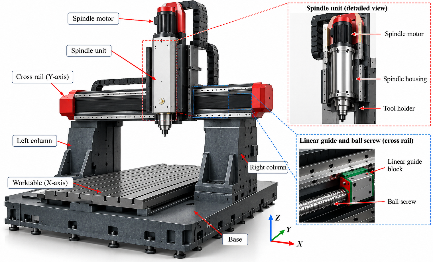
Finding where the machine was losing stiffness
The machine required high static stiffness and stable dynamic behaviour, but simply adding material would increase moving mass, drive demand and cost. The engineering task was to identify the load paths that controlled tool point compliance before any structural redesign was attempted.
Determine whether the spindle and gantry structure or the massive bed governed tool point movement under machining loads.
Establish the main structural modes and identify the regions most involved in low frequency machine motion.
Find where material could be redistributed or removed without sacrificing stiffness, interfaces or practical machine function.
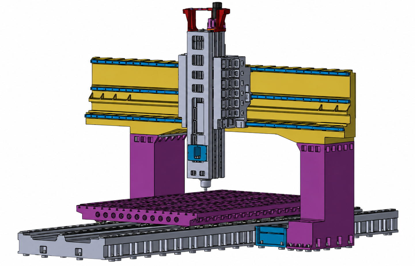
Validate the model before using it to redesign
The workflow combined CAD simplification, structural analysis and physical testing. After the numerical model showed good agreement with measured stiffness, it was used for static and dynamic interpretation before guiding structural optimization.
Build the structural model
Preserve the main load paths and represent machine interfaces realistically while simplifying nonessential geometric detail.
Compare with physical testing
Use measured stiffness at the spindle region to check whether the FE model reproduces the behaviour of the real machine.
Redesign the load path
Use the validated model to identify low contribution material, reconstruct practical geometry and reanalyse the revised structure.
Static FEA isolated the flexible load path
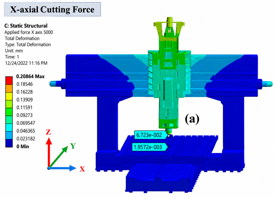
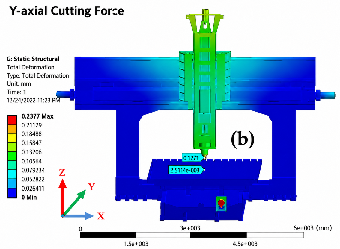
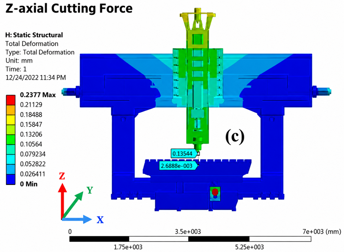
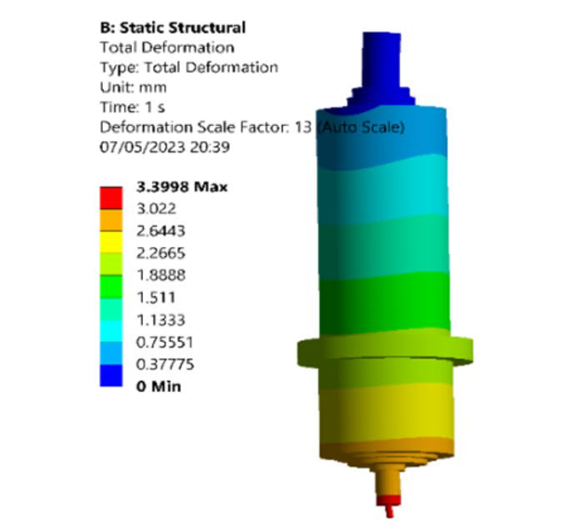
Representative cutting loads were applied in the three machine directions. Across the cases, deformation concentrated around the spindle and ram while the bed remained comparatively rigid. This established the upper machine structure as the more important target for stiffness improvement.
Tool point movement was much larger than bed movement, confirming that the compliance was concentrated in the spindle and gantry load path.
The vertical and lateral load cases produced the largest spindle response, helping prioritize where structural stiffness mattered most.
Testing confirmed the numerical model
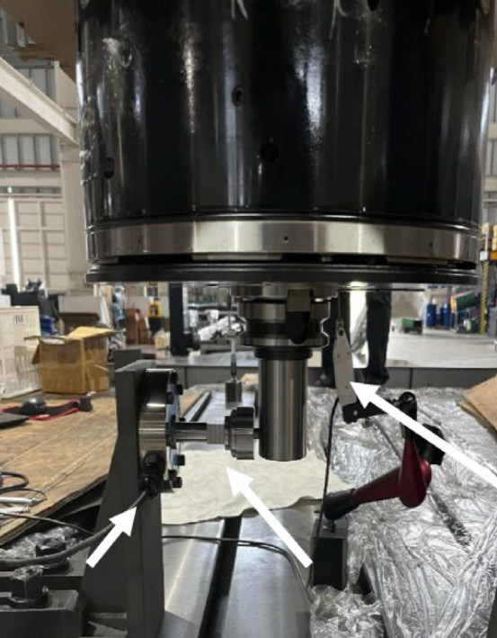
A physical stiffness test was carried out at the spindle using a controlled loading and displacement measurement arrangement. The measured response followed the same stiffness behaviour predicted by the FE model, giving confidence in the representation of the machine structure and its connections.
Measured and predicted stiffness differed by less than two percent in the principal comparison.
The close agreement supported using the model for modal interpretation and subsequent structural optimization rather than relying on simulation alone.
Material was redistributed around the load path
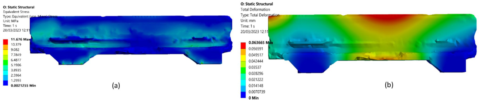
The validated model was then used to identify low contribution material in the large cross rail. The topology result was reconstructed into practical engineering geometry and reanalysed rather than being treated as a finished design directly.
The revised cross rail removed about eighteen percent of the reference mass.
Predicted deformation and equivalent stress both reduced after the redesigned load path was reanalysed.
The optimization was converted back into practical CAD and checked again through FEA before conclusions were drawn.
The important result was not simply identifying deformation. Physical correlation established enough confidence to use the model to distinguish the critical load path and redistribute material with a defensible engineering basis.
A stronger basis for machine redesign
The study moved from structural diagnosis through physical validation to practical optimization. The resulting workflow showed how simulation can support both performance improvement and material reduction when the model is first checked against the real machine.
The spindle and gantry load path, rather than the massive bed, controlled the dominant tool point compliance.
Physical stiffness testing closely matched the numerical prediction, supporting the use of the model for design decisions.
Modal and harmonic checks were used as supporting evidence to understand the global machine response without becoming a separate public case study section.
The cross rail redesign reduced mass while also improving the predicted structural response.