
40 ft GooseneckTrailer ChassisStructural Design
Structural development of a heavy duty gooseneck flatbed chassis around a 30,000 lb GVWR, with continuous longitudinal load paths, repeated transverse framing and local reinforcement at higher demand regions.
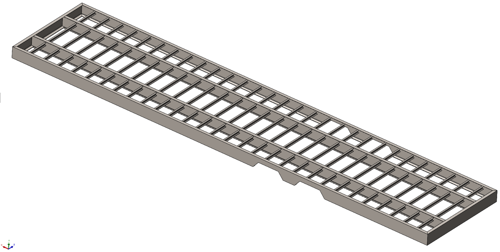
Carry the gross load through a predictable welded structure
At the required gross rating, cargo load had to be distributed between the forward towing interface and the axle and suspension group while the frame remained stiff enough for predictable handling and repeated road loading.
Fabrixon treated the chassis as a welded load carrying system rather than a simple deck frame. Longitudinal rails carry the dominant span forces, closely spaced crossmembers distribute deck load and reinforcement is concentrated where reactions or geometry changes increase demand.
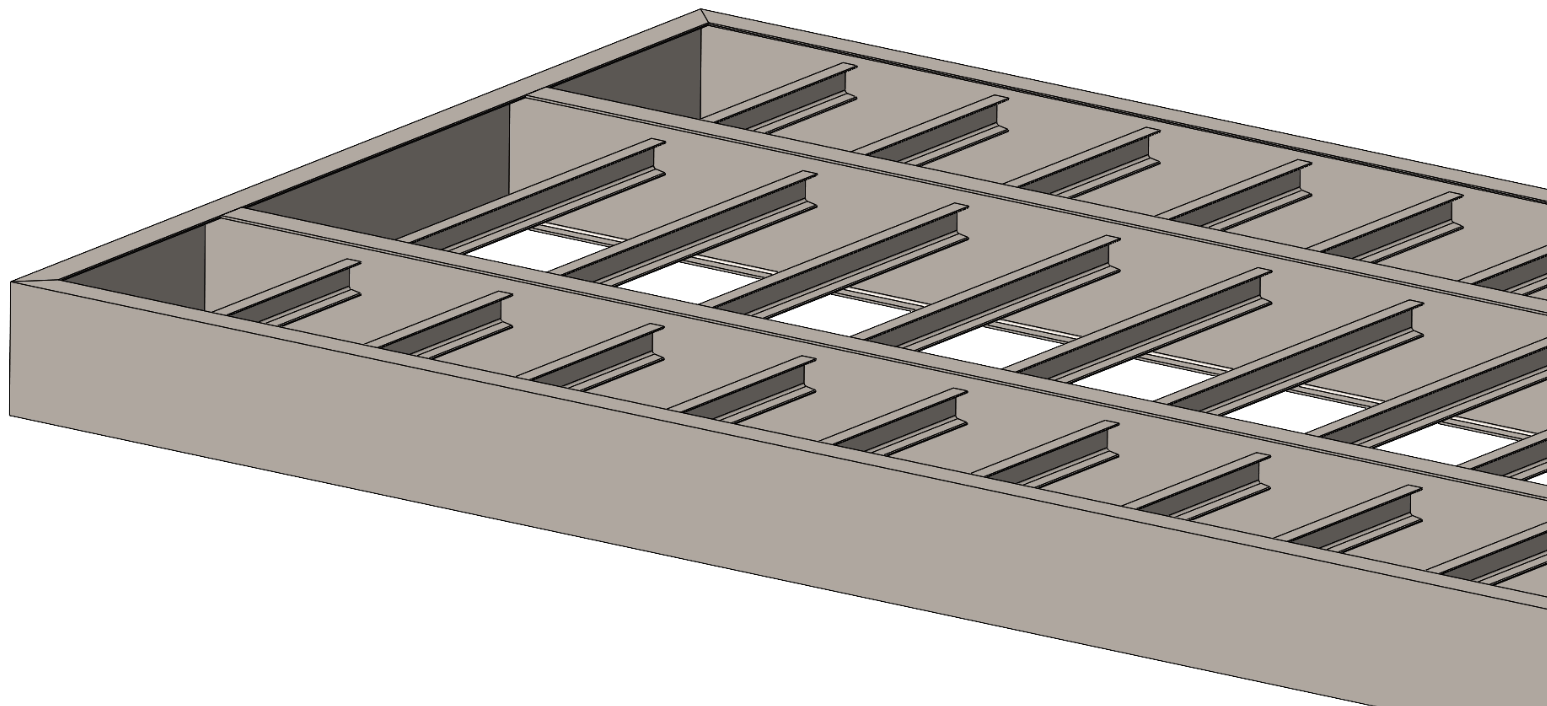
Use the rails and crossmembers as one structural system
The layout was developed around continuous longitudinal load paths and repeated transverse framing. This distributes local cargo reactions into the primary rails instead of allowing individual deck regions to behave independently.
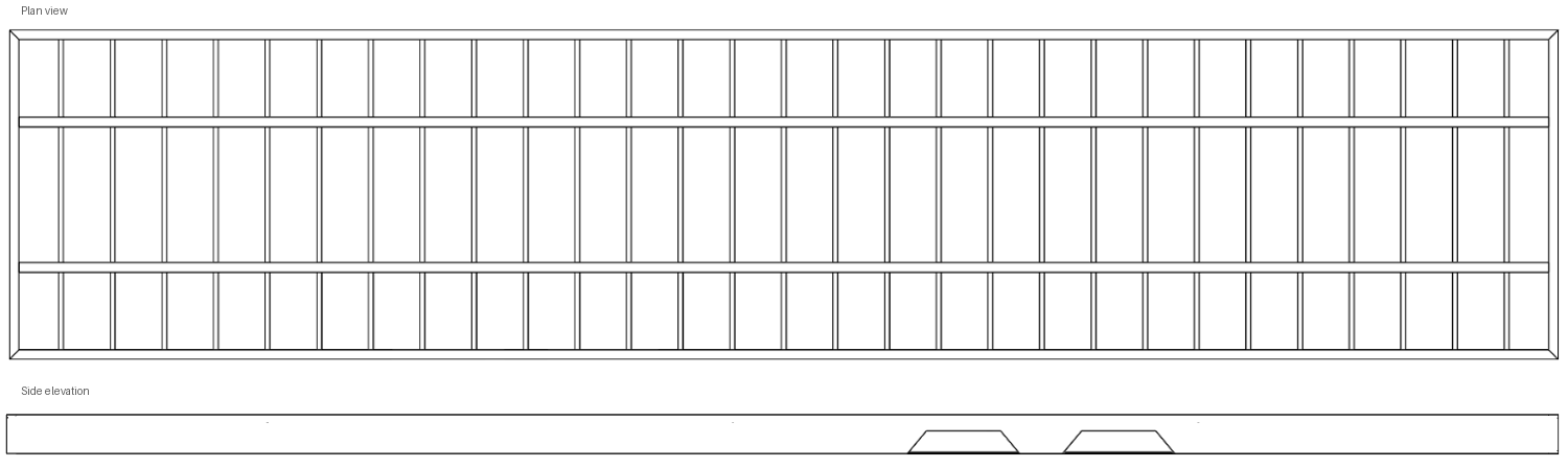
- Longitudinal rails
- Carry the dominant global span forces between towing and running gear reactions.
- Crossmembers
- Provide dense deck support and distribute local cargo or equipment loads into the main rails.
- Reinforcement
- Concentrated around geometry changes and reaction zones where local demand increases.
- Structural efficiency
- Member hierarchy was developed to protect payload capability without treating every region as equally loaded.
Check the load cases that drive chassis behaviour
The structural review considered the complete duty rather than one uniform deck case. Global bending, torsion, local reactions and serviceability all influence the welded chassis architecture.
- Distributed loading
- Cargo loading across the deck and primary longitudinal frame.
- Concentrated loading
- Equipment or wheel loads acting through a limited number of crossmembers.
- Asymmetric input
- One side road loading used to assess torsion and local racking.
- Longitudinal loading
- Braking and acceleration effects considered in the structural load path.
- Lateral loading
- Cornering and lane change effects considered at the chassis level.
- Local reactions
- Towing, suspension, axle and reinforcement interfaces treated as local demand zones.
- Serviceability
- Global deflection and relative chassis distortion included in the engineering review.
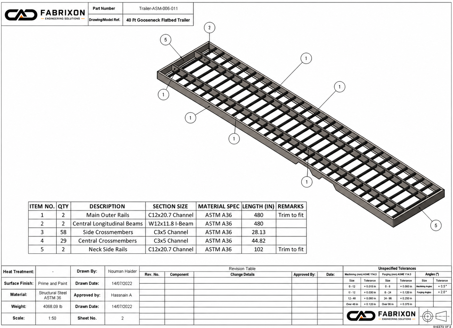
Translate the structure into a repeatable welded assembly
The chassis architecture was converted into a controlled manufacturing package defining the main rail hierarchy, repeated transverse members, local reinforcement zones and assembly relationships.
This documentation preserves the intended load path through manufacture and makes repeated chassis construction less dependent on shop interpretation.
- Member hierarchy
- Primary rails, repeated transverse members and local strengthening identified clearly.
- Assembly relationships
- Structural interfaces coordinated so the welded frame can be reproduced consistently.
- Manufacturing intent
- Documentation communicates the geometry required to preserve the engineered load path.
The completed chassis met the required structural envelope
The successful project delivered the required 40 ft structural platform around the 30,000 lb gross vehicle rating and the intended structural efficiency targets. Final road legal payload remains dependent on running gear, options and the completed vehicle configuration.
Completed structural platform length.
Required project gross duty achieved.
Structural efficiency target achieved within the project envelope.
Target envelope before option and configuration adjustments.
The towing interface context referenced SAE J2638 criteria for fifth wheel and gooseneck coupling structures up to 30,000 lb. This case study does not claim a separate certification or final road legal payload independent of the completed vehicle configuration.
Continuous load paths kept the chassis architecture structurally coherent
The solution worked because the main rails, repeated crossmembers and local reinforcement were developed as one load carrying system. Local reactions were introduced into a continuous structural hierarchy instead of being treated as isolated frame details.
A repeatable 40 ft chassis platform that achieved the required duty
The completed design established a coherent heavy trailer structure with continuous longitudinal load paths, dense transverse support and local strengthening at higher demand regions. The controlled engineering package carried that structural intent through to manufacture.
- Project result
- The 40 ft chassis successfully met the required 30,000 lb structural duty.
- Load path
- Primary rails and repeated crossmembers distribute global and local demand through a coherent frame.
- Structural efficiency
- The design achieved the intended tare and payload efficiency envelope for the project configuration.
- Documentation
- A controlled manufacturing package defined the structural member hierarchy and assembly relationships.