
Large Tonnage AutomotiveExterior Panel Mould
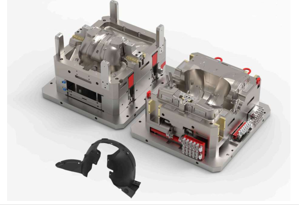
Large scale injection mould engineering for a matched left and right hand automotive fender pair, combining Class A surface control, zoned cooling, controlled filling, ejection and mould base validation.
Client identity, proprietary panel geometry, cavity dimensions, hot runner sizing, cooling details, support sizing and FEA limits are withheld.
Client identity, proprietary panel geometry, cavity dimensions, hot runner sizing, cooling details, support sizing and FEA limits are withheld.
Keep large cosmetic panels dimensionally stable
The mould had to control dimensional fit, visible surface quality, sink risk, weld line position and warpage across broad thin exterior geometry while carrying high injection and clamp loads.
At approximately 26 tonnes, the tool also required coordinated handling, support and manufacturing documentation rather than cavity development in isolation.
Large thin exterior panels had to remain dimensionally compatible with adjacent vehicle bodywork.
Sink, pressure marks, uncontrolled flow interaction and weld lines had to be managed away from cosmetic surfaces.
Independent cooling zones were needed to reduce temperature gradients and differential shrinkage across the tool.
The mould base had to resist clamp and injection loads while pins and lifters released the panel without visible marking.
Coordinate mirror cavities, cooling and controlled filling
The tool was configured to produce one left hand and one right hand fender per cycle. Cavity layout, support pillars, guide elements, runner strategy and independently circuited cooling zones were developed as one system for the 1,500–2,000 tonne press class.
Gate placement and valve sequencing were used to manage long flow paths and move visible flow interactions away from critical surfaces.
- Cavity arrangement
- Matched left and right hand exterior panel pair in one mould.
- Cooling
- Independent zones developed around the large cavity surfaces.
- Filling
- Controlled multi gate strategy for long flow paths and weld line management.
- Press envelope
- Mould architecture sized around the 1,500–2,000 tonne class.
Control mould deflection and release without surface marking
Structural FEA checked mould base deflection under clamp and injection pressure so parting line contact could remain controlled without unnecessary mass. The release system distributed ejector and lifter loads across the panel while keeping witness marks away from visible surfaces.
- Structural check
- FEA validation of the mould base under clamp and injection pressure.
- Ejection
- Pins and lifters distributed release load and cleared local undercuts.
- Handling
- Dedicated provisions included for an approximately 26 tonne tool.
- Documentation
- PDF, DWG and STEP outputs with texture mapping and handling interfaces.
Meet the specified exterior panel operating requirements
The completed project achieved the required production duty for the matched exterior panel pair. Exact higher results are not published where the successful tool exceeded the original specification.
Required pair per cycle achieved.
Specified large panel cycle range achieved.
Required zone uniformity achieved.
Specified exterior functional finish achieved.
The mould remained designed around the recorded 1.5–2.2 million shot service target. That value is retained as a durability design requirement rather than a claim that the public record contains an accumulated shot count.
For Class A panels, mould stiffness is part of surface quality
Cooling strategy alone cannot protect a broad cosmetic panel if the backing structure deflects under pressure. The project linked filling, thermal balance, ejection and structural support so the visible part geometry and the tool structure were validated together.
The completed tool delivered the required large panel production envelope
The successful project brought cavity design, thermal management, controlled filling, ejection and mould base structure into one coordinated production solution for a large automotive exterior application.
- Press class
- Tool sized around a 1,500–2,000 tonne press envelope.
- Tooling scale
- Approximately 26 tonne mould with dedicated handling provisions.
- Production duty
- One left and one right panel per cycle at the specified 28–36 second duty.
- Validation
- Structural FEA used for deflection control under clamp and injection loading.