
Gooseneck TrailerChassis Static FEA
Static structural assessment of an OEM supplied trailer chassis, with load application, mesh refinement and documented results supporting the design release.
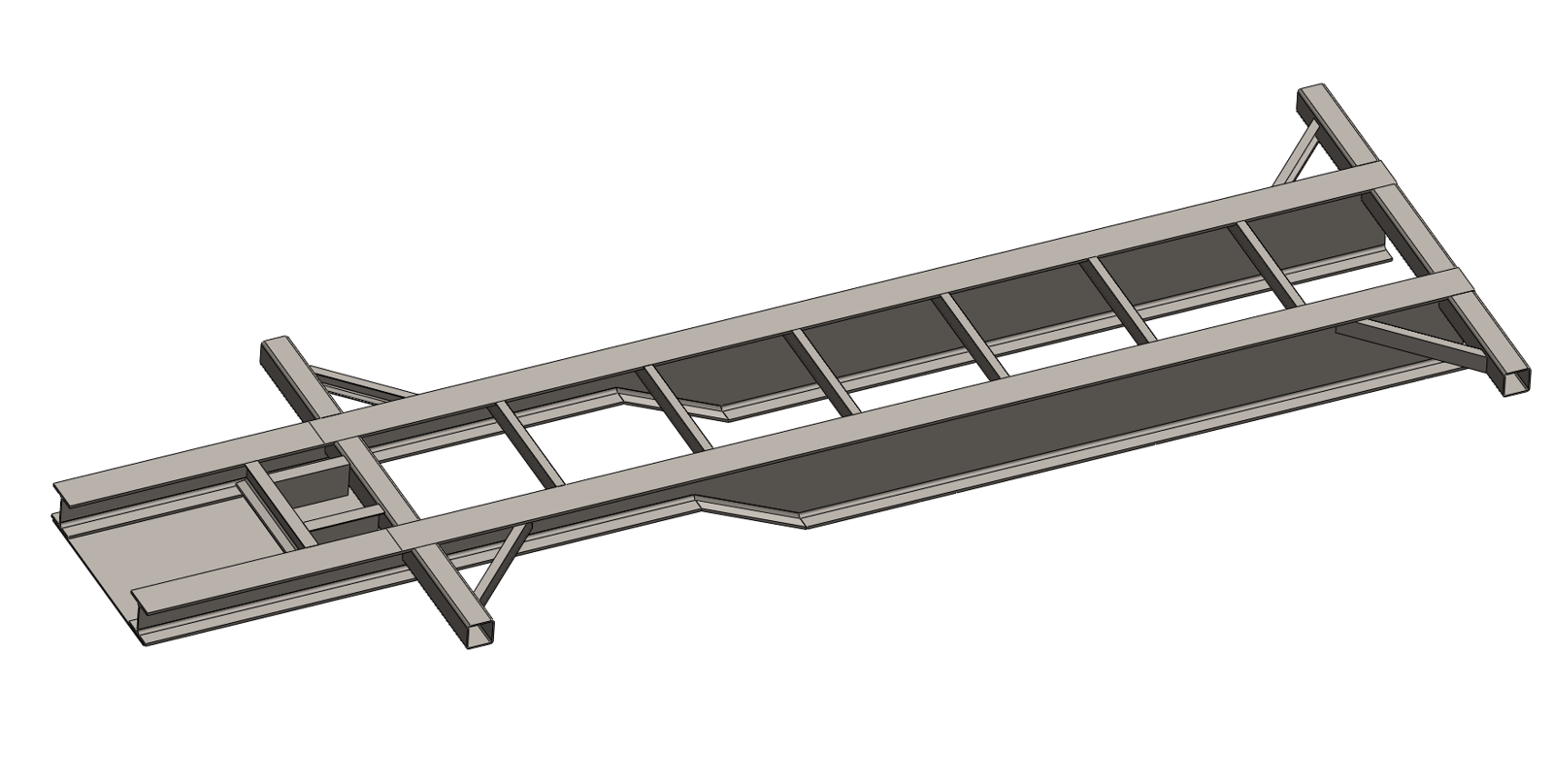
- Objective
- Provide design release evidence
- Method
- Static structural FEA
- Boundary
- OEM retained chassis design
- Outcome
- Validation report delivered
Assess the design the OEM supplied
Fabrixon’s scope was structural validation rather than chassis redesign. The OEM retained the customer specification, chassis design, fabrication and eventual certification submission.
Load distribution, material specification and support assumptions were reviewed before analysis. The report needed to make those inputs traceable so the OEM could interpret the stress and displacement results within the stated load case.
- Structure
- 40 ft gooseneck trailer chassis supplied by the OEM.
- Payload
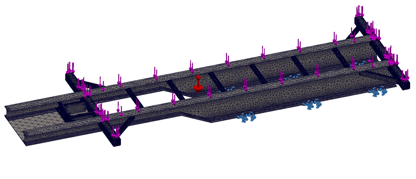
- 40,000 lb design payload with the distribution defined by the OEM.
- Assessment
- Static linear FEA in ANSYS Mechanical against the stated 250 MPa material yield reference.
- Release package
- Document model assumptions, convergence work, stress results and displacement output for engineering review.
Build credibility into the model
Shell representation was used where appropriate, with solid regions where local behaviour required more detail. Mesh refinement focused on the gooseneck transition, attachments and other geometric concentrations.
- 01
Prepare
Import the chassis and retain geometry that governs the structural load path.
- 02
Apply
Use the specified payload distribution and the agreed coupling and suspension reactions.
- 03
Refine
Reduce local element size until results stabilise within the project convergence tolerance.
- 04
Report
Record the material basis, mesh checks, peak stress and displacement interpretation.
A margin within the stated case
The reported converged peak was below the material yield value used in the model. These figures describe the supplied static payload case; they are not a road durability or fatigue rating.
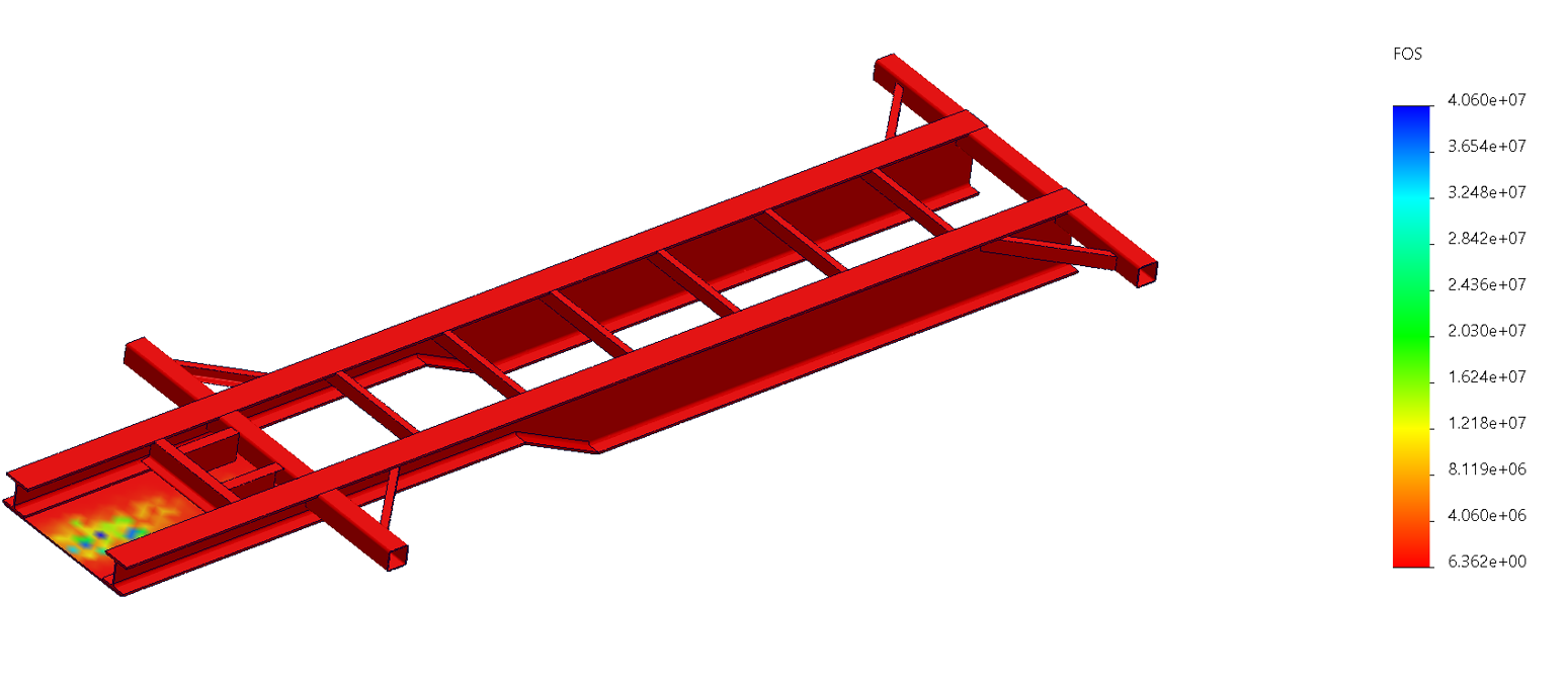
Factor of safety
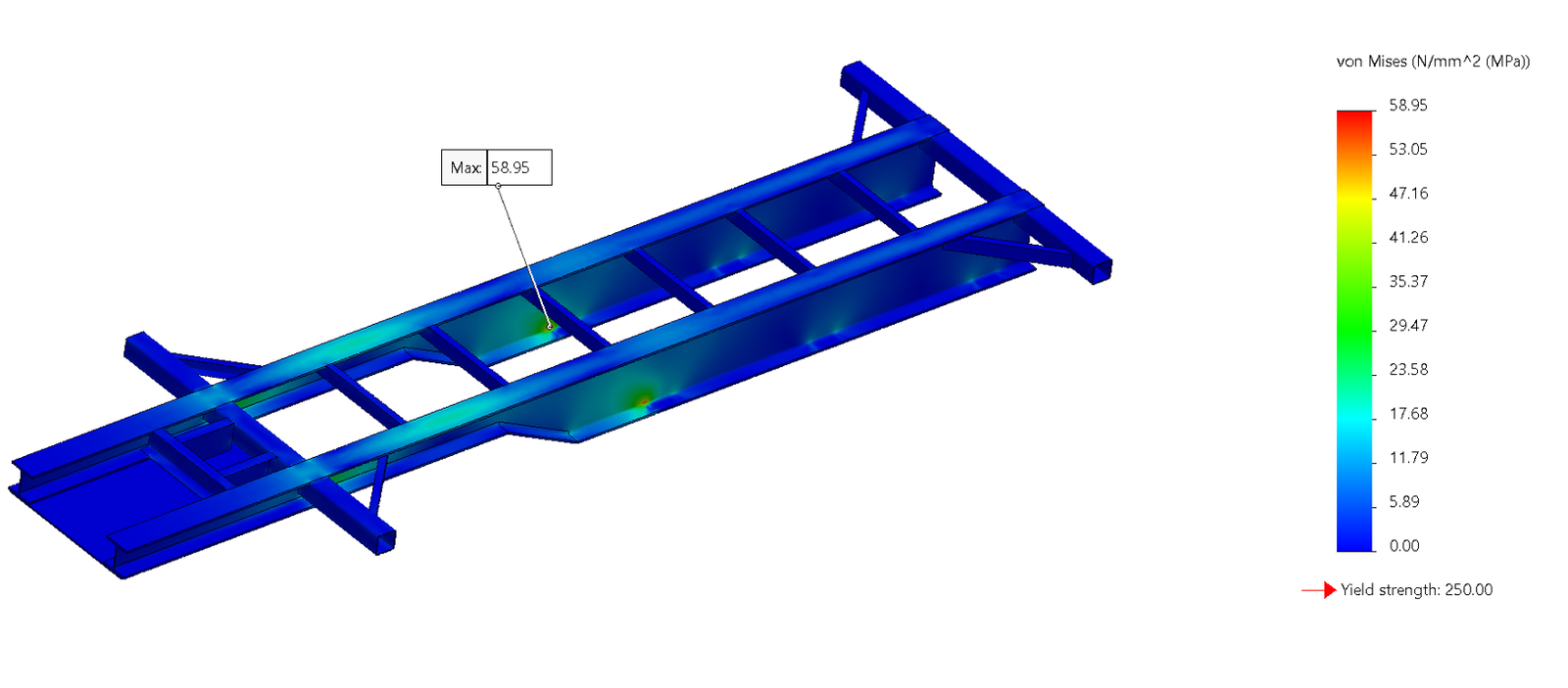
Von Mises stress
Total deformation
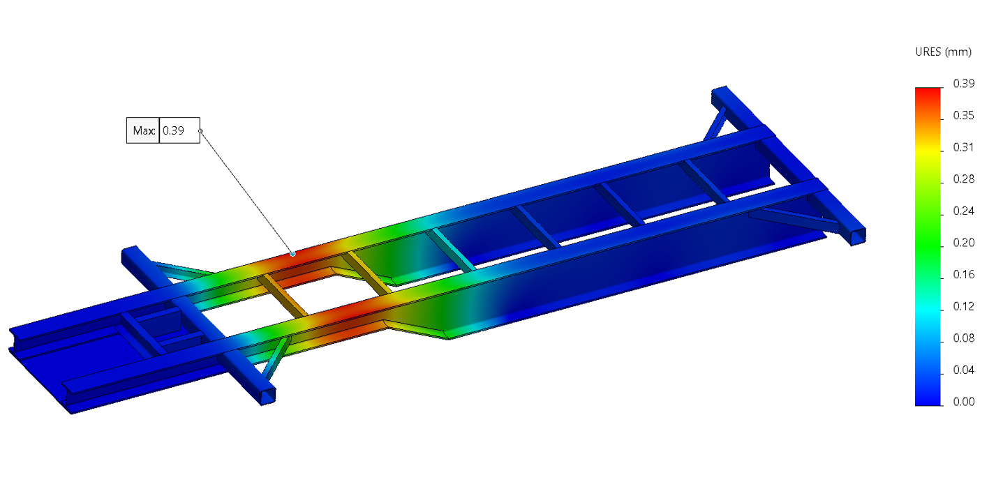
| Result | Value | Interpretation |
|---|---|---|
| Peak von Mises stress | 59 MPa | Rounded converged peak |
| Stress relative to yield | 24% | Of the stated 250 MPa material yield |
| Implied yield ratio | 4.2 | For this static load case |
| Maximum displacement | 0.39 mm | Reported URES peak for the modelled case |
| Displayed FOS floor | 6.36 | Lowest mapped value shown on the presented factor of safety plot |
The material reference was ASTM A36 with the stated yield value used in the model. Stress is rounded for presentation; the result is bounded by the specified static load distribution.
Static validation is a bounded scope
The report supported the OEM’s design release using a specified payload case. Its scope boundary matters as much as the headline stress result.
Included in this assessment
Static load application, support assumptions, stress and deformation assessment, mesh refinement and documentation of the analysis basis.
Not established by this result
Road shock response, peak dynamic suspension reactions and fatigue performance under service history. These remain separate analyses from this static assessment.
A documented basis for release
The validation report was delivered on schedule and the chassis was released for fabrication. Fabrixon remained available to clarify assumptions and analysis scope during the release process.
- Responsibility
- Fabrixon supplied analysis evidence; the OEM retained design ownership, manufacture and certification.
- Traceability
- The report recorded the model, specified loads, material references and mesh refinement approach.
- Scope recorded
- Static evidence supported the release review, while dynamic loading and fatigue were identified as separate assessment scopes.