Flow Simulation for Residential Kitchen Ventilation & Heat Transfer
Executive Summary
Fabrixon conducted a detailed Computational Fluid Dynamics (CFD) study to evaluate ventilation and heat transfer in a standard residential kitchen during cooking operations. Using SOLIDWORKS Flow Simulation, the project analyzed real-world thermal loads from gas burners and an oven to verify air quality, temperature distribution, and occupant comfort. Results showed that the exhaust hood successfully captured over 85% of heat and fumes, maintaining the average kitchen temperature below 30 °C and ensuring thermal comfort near the cooking zone. The simulation confirmed that the proposed ventilation layout provided efficient airflow circulation, minimized stagnant air pockets, and eliminated the need for costly post-installation adjustments. This study demonstrates Fabrixon’s capability to apply CFD tools to optimize real-world HVAC and ventilation designs for residential environments.
Problem Statement
A residential kitchen design required analysis of airflow and heat transfer to ensure comfortable conditions during cooking. The objective was to verify that ventilation effectively removed hot air and cooking fumes, prevented heat buildup near occupants, and maintained a safe, energy-efficient environment.
Key challenges included:
- Lack of test data – Only the CAD layout of the kitchen was available, with no prior performance evaluation.
- Overheating risks – Cooking appliances such as the stove and oven were expected to generate localized hotspots.
- Ventilation effectiveness – Airflow paths needed validation to confirm that heat and fumes moved toward the exhaust rather than recirculating.
- Design restrictions – Fixed window and door placements limited airflow adjustment options.
The goal was to carry out a CFD simulation study to predict temperature distribution, airflow behavior, and ventilation performance before installation.
Our Engineering Solution
Using SOLIDWORKS Flow Simulation, our engineering team executed a complete CFD workflow from geometry preparation to post-processing. The simulation replicated real cooking conditions, measured thermal comfort, and validated ventilation efficiency.
The study focused on:
• Modeling the kitchen space including stove, oven, windows, and exhaust hood.
• Assigning realistic heat generation values for the cooking appliances.
• Defining airflow through natural ventilation (windows/doors) and forced extraction (range hood).
• Providing data-driven design improvements to achieve balanced ventilation.
How We Approached the Problem
1. Geometry Preparation & Setup
• Verified geometry integrity and ensured a watertight domain.
• Applied lids at inlets (window/door openings) and outlet (exhaust hood).
• Simplified non-essential features for efficient meshing.
2. Boundary Conditions & Fluid Properties
• Inlets: Fresh air entering through windows/doors at 22 °C.
• Outlet: Exhaust hood modeled at negative pressure, simulating fan extraction.
• Heat Sources: Four stove burners at 2 kW each (8 kW total) and an oven at 3.5 kW.
• Walls: Treated as adiabatic, except near stove where conduction through wall layers was included.
3. Kitchen Domain & Ventilation Setup
• Typical kitchen dimensions: 4.2 m × 3.0 m × 2.6 m (≈ 33 m³ volume).
• Exhaust airflow rate: 650 m³/h (≈ 12 air changes per hour).
• Natural inlet airflow ensured pressure balance for proper exhaust efficiency.
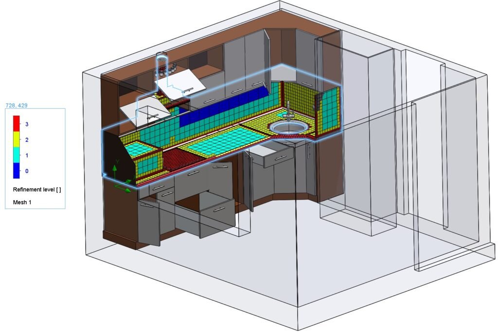
4. Meshing & Solver Settings
• Global mesh level = 5 with local refinements near stove, hood, and occupant zone.
• Boundary layer mesh enabled for near-wall heat transfer.
• Turbulence model: RNG k–ε with buoyancy effects.
• Radiation model: Surface-to-Surface (S2S).
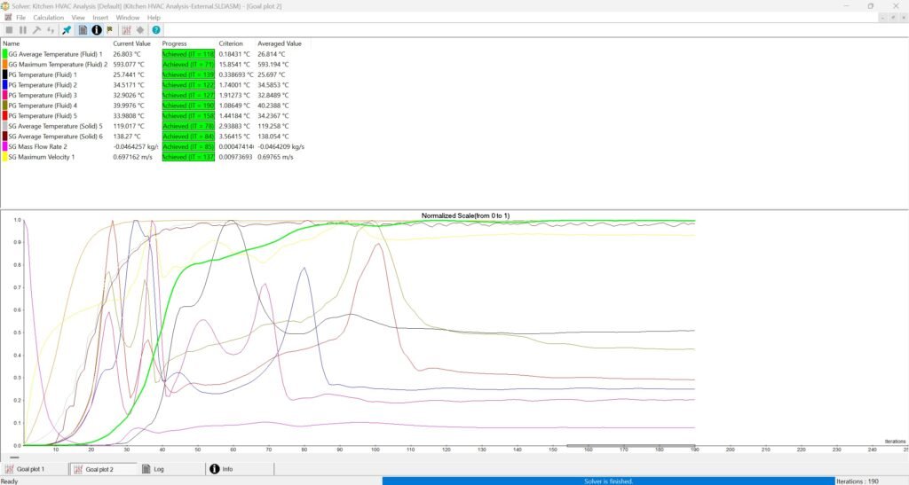
• Simulation run until mass and energy imbalance < 1%.
5.Goals & Convergence Criteria
• Surface goals: Pressure and temperature at inlets and outlet.
• Global goals: Average kitchen temperature, maximum velocity, and heat removal rate.
• Equation goals: Overall heat transfer rate and pressure drop across the space.
Key Results & Client Benefits
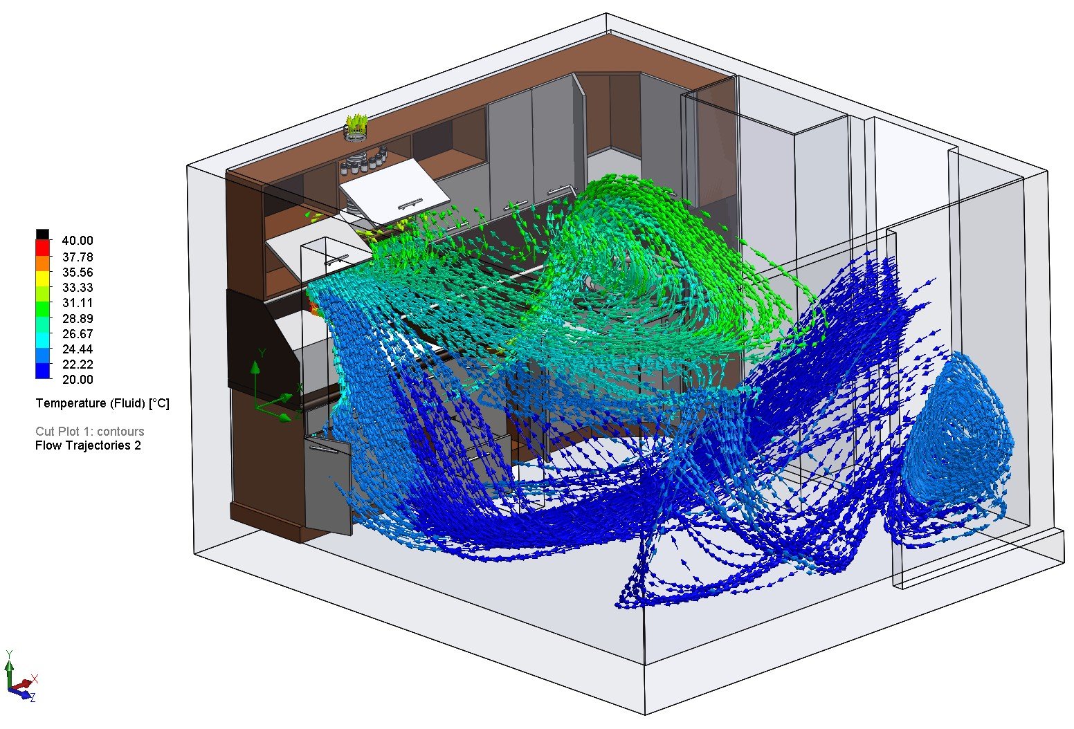
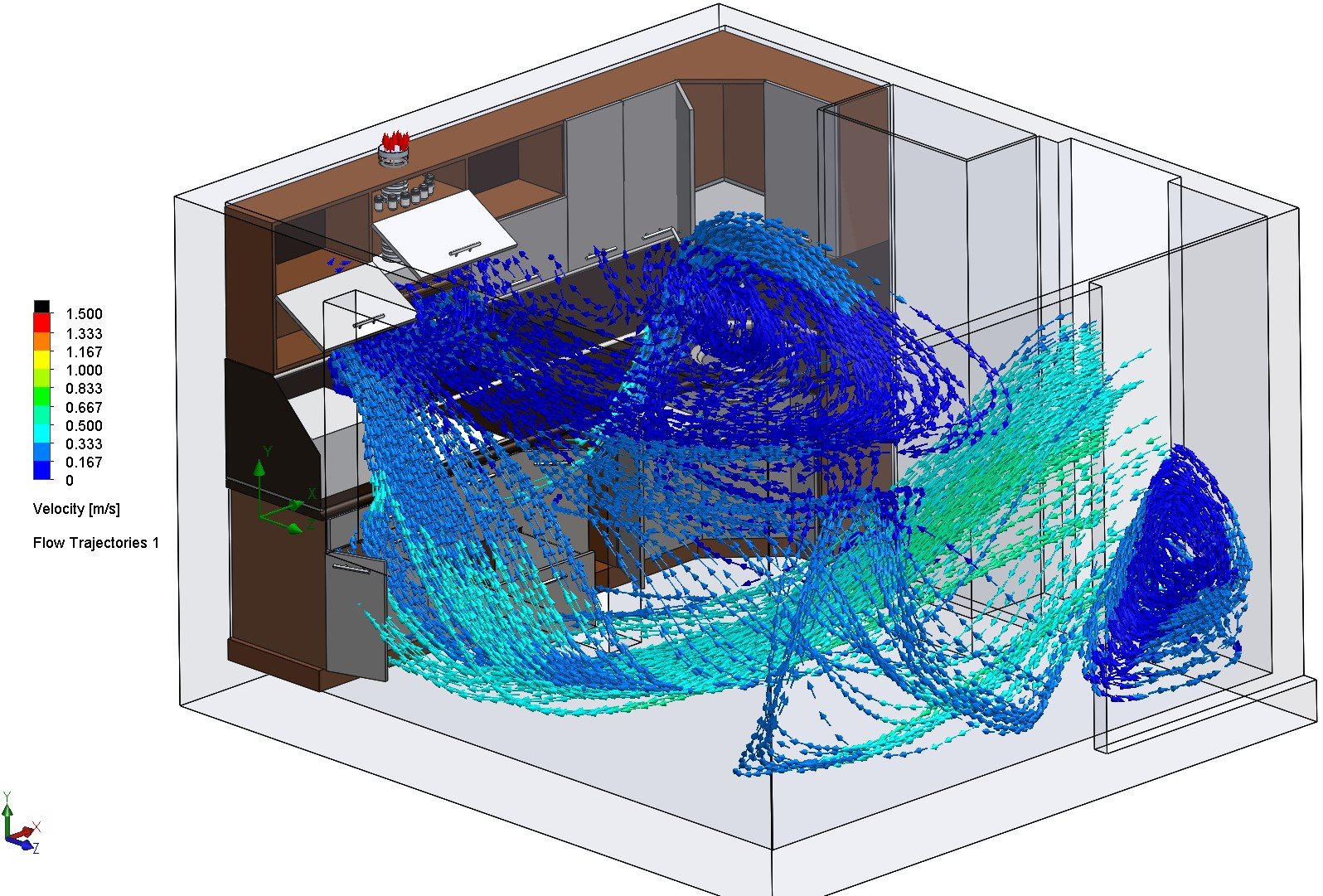
Flow Trajectories: Hot air from the stove was effectively captured by the exhaust hood, with clear upward plumes and minimal recirculation.
Velocity Distribution: Average airspeed near the cooking zone ≈ 0.35 m/s; weak airflow zones identified in the far corner (< 0.1 m/s).
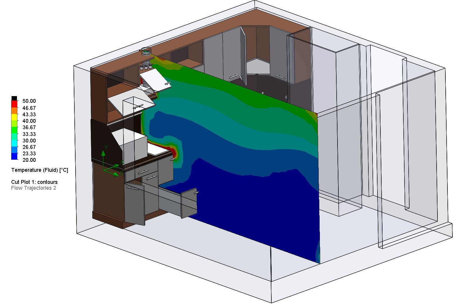
Temperature Distribution:
• Peak air temperature ≈ 66 °C just above the stove (5 mm above surface)
• Average room air temperature ≈ 28 °C
• Breathing zone (1.7 m height) < 29 °C
Ventilation Efficiency: Exhaust system captured ≈ 85% of generated heat and fumes under steady-state operation.
Technical Highlights
• Kitchen volume: ≈ 33 m³
• Heat load: 8 kW (stove) + 3.5 kW (oven)
• Exhaust rate: 650 m³/h (12 ACH)
• Inlet air: 22 °C, outlet via negative pressure hood
• Models: RNG k–ε turbulence, S2S radiation, steady-state
• Results:
– Peak temperature ≈ 66 °C above stove
– Average kitchen ≈ 28 °C
– Ventilation efficiency ≈ 85%
Key Results & Benefits
- Improved Air Quality – Efficient fume extraction reduced indoor pollutant recirculation.
- Thermal Comfort Verified – Occupant temperatures maintained below 30 °C.
- Energy-Efficient Design – Balanced inlet/extraction flow ensured uniform air distribution.
- Reduced Risk Before Installation – Performance validated before construction, saving cost and time.
Conclusion
This CFD-based study provided valuable insights into ventilation performance and thermal behavior in a residential kitchen. The results confirmed that the proposed design achieved effective heat removal, maintained occupant comfort, and ensured safe operation during cooking. By integrating simulation early in the design process, Fabrixon validated performance before installation — minimizing risk, ensuring energy efficiency, and confirming that the ventilation system met both technical and comfort standards.