Precision CAD Drafting for Heavy-Duty Machined Pivot
Bracket
Problem Statement
Statement: A leading manufacturer of automated production equipment required detailed manufacturing documentation for a critical pivot mounting
bracket used in their robotic assembly systems. They faced complex engineering challenges:
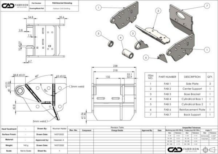
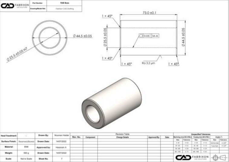
• Precision machining requirements – Precision-bored cylindrical boss for shaft mounting with tight tolerances
• Multi-directional loading – Complex robotic arm movements requiring careful stress analysis
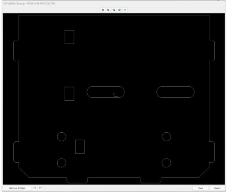
• Mixed manufacturing methods – Combination of laser cutting, CNC machining, and precision boring operations
• Component integration – Multiple mounting interfaces for electrical, pneumatic, and mechanical connections
• Quality critical application – Any dimensional errors would cause expensive robotic system failures
The goal was to convert their concept sketch into production-ready documentation that would prevent expensive robotic system failures and enable both
prototype and high-volume production.
Our Engineering Solution
Using comprehensive CAD drafting and manufacturing engineering services, we conducted a 4-day intensive development program transforming the concept
into production-ready documentation. Our approach was designed to:
• Analyze optimal production sequences combining laser cutting and CNC machining operations
• Create detailed 3D models with all geometric features and critical tolerances
• Generate complete manufacturing documentation with GD&T tolerancing for critical features
• Establish quality control procedures and inspection requirements for consistent production
How We Approached the Problem
1. Requirements Analysis & Manufacturing Planning
We analyzed robotic system mounting requirements and load conditions, determined critical dimensions and tolerance requirements for the shaft interface, and established the manufacturing sequence for optimal accuracy and efficiency. Our team selected appropriate material specifications for strength and machinability while creating a preliminary 3D model for manufacturing feasibility review.
2. Detailed CAD Development & Tolerancing
We developed a complete 3D model with all geometric features and relationships, applied GD&T tolerancing system for critical functional dimensions, and generated detailed views showing all machining features and specifications. The team created inspection drawings with coordinating measuring requirements and validated the design for manufacturability and quality control procedures.
Disclaimer: Due to client confidentiality and proprietary restrictions, highly toleranced plate drawings and detailed manufacturing files cannot be shared. All information and visuals presented in this case study have been reviewed and shared with the client’s consent for demonstration purposes only.
3. Manufacturing Process Engineering
Our engineers analyzed optimal production sequences combining laser cutting and CNC machining, determined work holding strategies for precision boring operations, and established inspection points and quality control procedures. We selected appropriate cutting tools and machining parameters while defining surface finish requirements for critical interfaces.
4. Documentation Completion & Quality Integration
We produced comprehensive manufacturing drawing packages, generated CNC ready cutting files with material optimization, and created machining operation sheets with setup and tooling details. The team provided quality control documentation and inspection requirements with complete revision control and change management systems.
Key Results & Client Benefits
Manufacturing Excellence Achieved All dimensions met specification without revision on first article success, with the precision bore achieving H7 tolerance class consistently. The bracket achieved 100% inspection pass rate across the production run, with all machined surfaces exceeding specification requirements and optimized manufacturing sequence reducing cycle time by 30%.
Exceptional Return on Investment
- Immediate value delivered through prevented precision manufacturing errors, optimized manufacturing sequence, eliminated design iterations, and quality system implementation
- $1.35 million annual production benefits from manufacturing cost reduction and quality cost avoidance
- 814% immediate ROI with ongoing annual benefits demonstrating exceptional value
Technical Precision Delivered
The bracket featured a precision bore of 50mm diameter x 30mm length, precision bored to ±0.01mm with H7 tolerance class for precision shaft fit. Material specification was 4140 Steel, heat treated to 28-32 HRC for durability, with dimensional accuracy of ±0.02mm on critical mounting surfaces and surface finish of 125 microinch on machined surfaces.
System Performance & Reliability
The robotic assembly system achieved ±0.1mm positioning accuracy with zero bracket failures in 18 months of continuous
operation. The documentation enabled seamless volume production with multiple shops able to manufacture from drawings, while the established inspection
procedures ensured ongoing quality control.
Conclusion
Through our precision CAD drafting and manufacturing engineering services completed in just 4 days with a $1,750 investment, we transformed complex component requirements into cost-effective production solutions. The 814% immediate ROI, combined with $1.35M in annual production benefits, illustrates the exceptional value of professional engineering services for precision manufacturing applications. When dimensional accuracy, production efficiency, and quality control are critical to business success, this project demonstrates how advanced CAD drafting delivers measurable results through manufacturing excellence. The success led to Atlas Manufacturing Systems designating Fabrixon as their preferred engineering partner for all precision component development, demonstrating the long-term value of technical expertise and measurable results.