CFD Analysis of Heat Exchanger for Industrial Thermal
System
Executive Summary
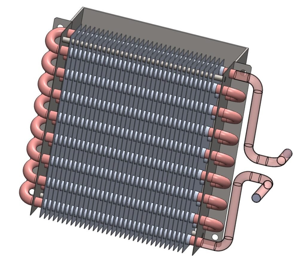
A CFD study was performed on a finned-tube heat exchanger to validate its performance under real operating conditions. Using SolidWorks Flow Simulation with heat conduction enabled, we modeled refrigerant-side and air-side flows to analyze temperature distribution, pressure drop, and thermal conduction through copper tubes and aluminum fins. Results confirmed the exchanger achieves the required ~45 °C temperature drop while maintaining safe material limits and acceptable pressure losses, allowing the client to move confidently toward prototyping.
Problem Statement
The client required validation of their heat exchanger design before manufacturing. Key questions included:
Will the refrigerant cool sufficiently (target temperature drop across tubes)?
Are fin and tube wall temperatures safe for continuous operation?
Is the pressure drop compatible with the pumping system?
Can the CFD analysis highlight potential performance optimizations?
Our Engineering Solution
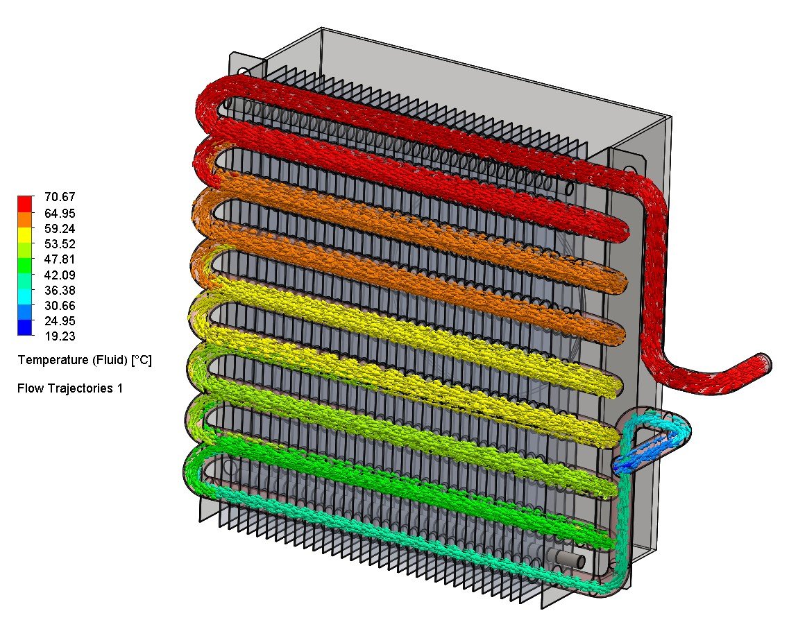
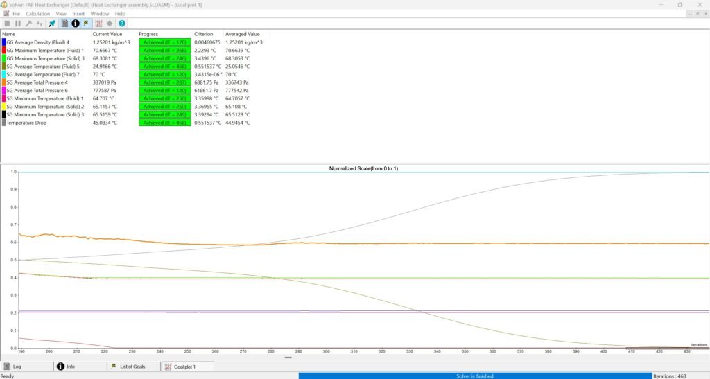
Temperature Drop: 45.08 °C across refrigerant confirmed design efficiency.
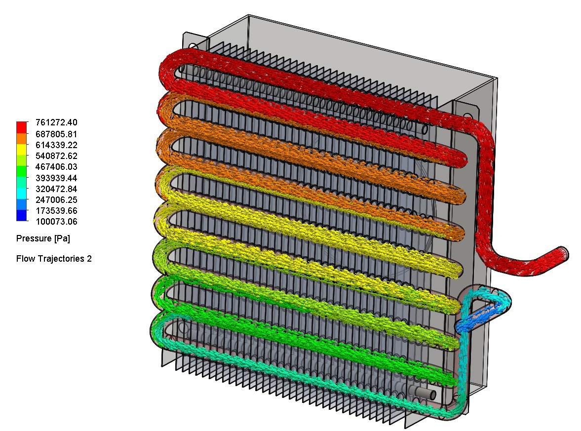
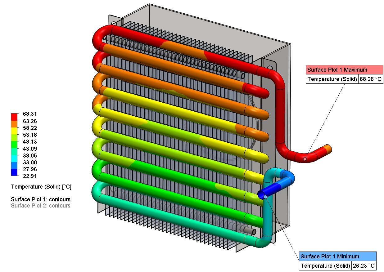
Outlet Conditions: Refrigerant cooled from ~70 °C to ~26 °C; pressure drop ~373,701 Pa.
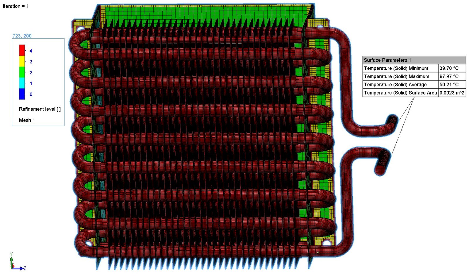
Tube Wall Temperatures: Max ~65.5 °C (safe for copper).
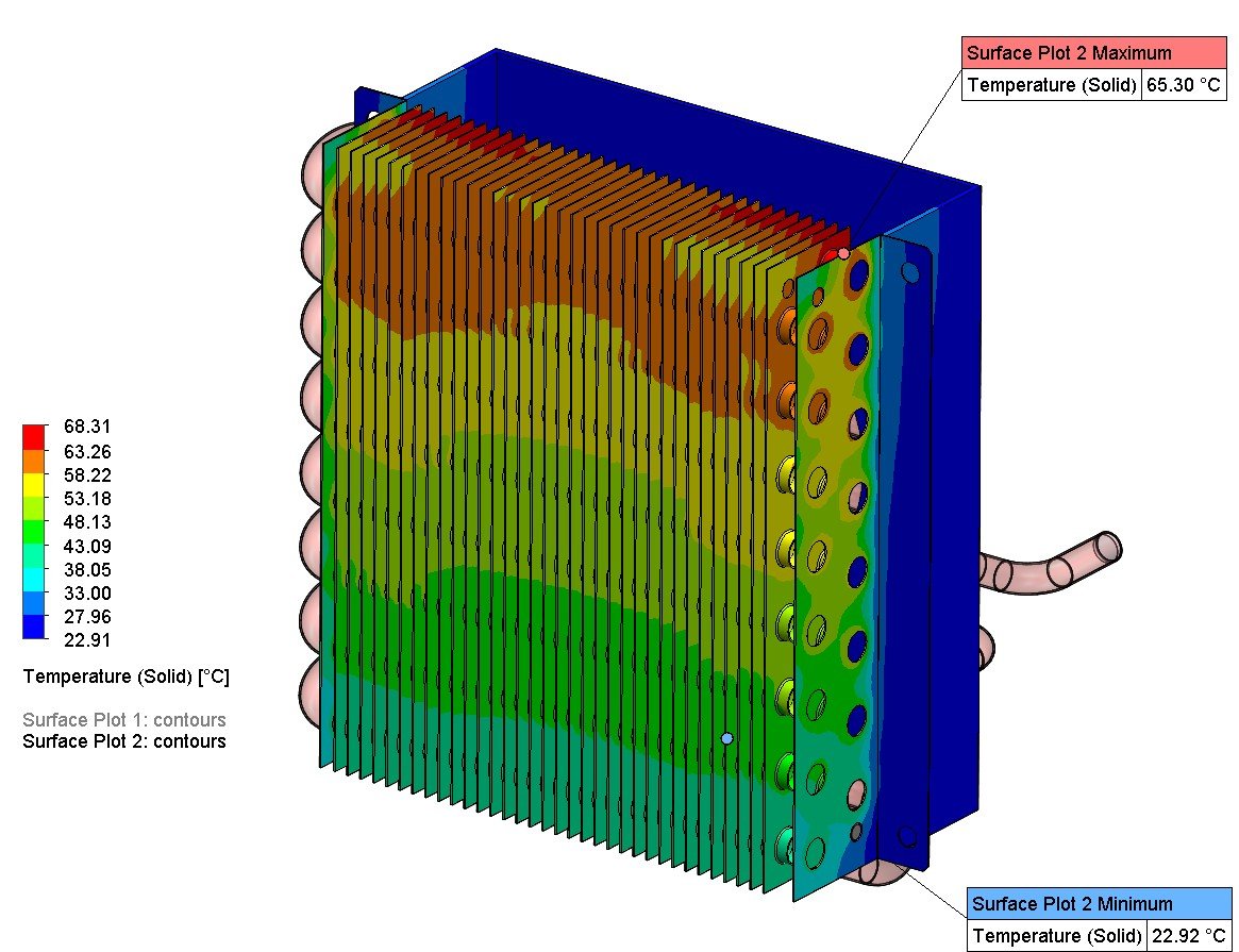
Fin Plate Temperatures: Surface plot confirmed uniform heat rejection.
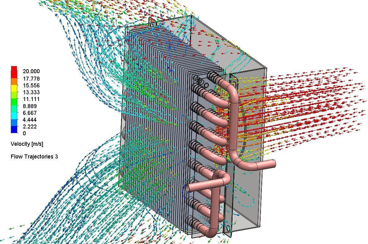
Flow Distribution: Balanced, no bypass or localized overheating.
Results & Visualization
Temperature Drop: 45.08 °C across refrigerant confirmed design efficiency.
Outlet Conditions: Refrigerant cooled from ~70 °C to ~26 °C; pressure drop ~373,701 Pa.
Tube Wall Temperatures: Max ~65.5 °C (safe for copper).
Fin Plate Temperatures: Surface plot confirmed uniform heat rejection.
Flow Distribution: Balanced, no bypass or localized overheating.
Key Results & Client Benefits
Validated Cooling Duty: 45 °C drop achieved.
Safe Operating Limits: Copper tubes and aluminum fins well within material thresholds.
System Efficiency: Pressure drop acceptable within pump/fan specs.
Risk Reduction: Insights confirmed design before costly prototyping.
Actionable Insights: Visualization pinpointed areas for potential optimization.
Conclusion
The CFD study validated the heat exchanger’s performance under realistic operating conditions. By combining system-level and component-level insights, we ensured the client’s design met thermal, structural, and efficiency targets. This provided the confidence to move forward with manufacturing while reducing development costs and timelines.
Designing heat exchangers or thermal systems?
Get simulation-driven validation to cut prototyping costs and boost reliability.