
Ever been stuck on a project where unclear sketches or misaligned plans caused confusion, delays, or even costly errors? It’s a common challenge in construction, architecture, and engineering when design communication isn’t precise; the entire project suffers.
This is where CAD drawings step in. With computer-aided drafting, professionals can create accurate 2D and 3D blueprints, reduce mistakes, and ensure everyone from architects to contractors works from the same reliable design. CAD drawings improve collaboration, speed up approvals, and provide a foundation for safe, cost-effective projects.
We’ll explore the main types of CAD drawings, including construction drawings, shop drawings, as-built documentation, and specialized drafting, along with the CAD software and modelling techniques that make them possible, their benefits, and how to choose the right tools for your projects.
Overview of Cad Drawing
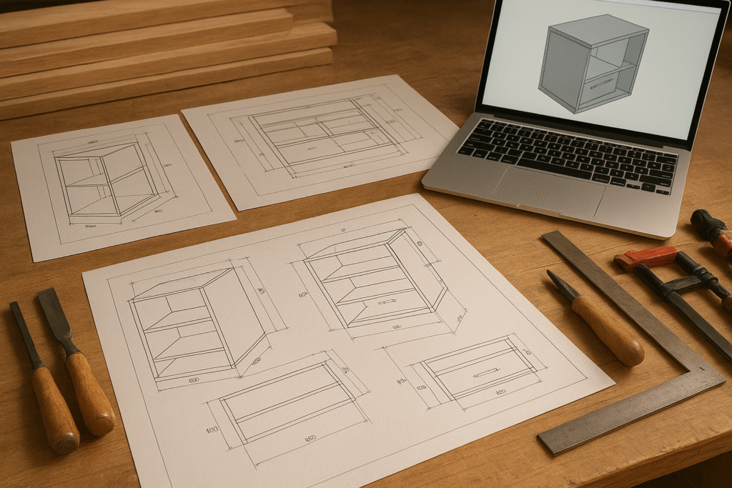
Computer-Aided Design (CAD) drawings are digital representations used in architecture, engineering, and construction to plan, design, and document projects with precision. Unlike manual sketches, CAD drawings provide accurate 2D and 3D blueprints that streamline communication between architects, engineers, contractors, and clients.
➤ What are CAD drawings?
CAD drawings are computer-generated technical drawings that include floor plans, elevations, sections, shop drawings, and as-built documentation. They serve as the foundation for building design, manufacturing, and product development by ensuring every measurement, layout, and detail is precise.
➤ Importance of CAD drafting in construction, architecture, and design
CAD drafting is vital because it:
- Improves accuracy and efficiency compared to manual drafting.
- Reduces errors and costly mistakes in projects.
- Supports construction drawings, interior drafting, millwork drafting, and furniture shop drawings for specialized needs.
- Enhances collaboration across disciplines such as architectural, mechanical, and electrical CAD.
- For instance, understanding what a Schematic Diagram is crucial for electrical CAD, while mechanical engineers often apply advanced simulations, such as Computational Fluid Dynamics in CAD Modeling and Finite Element Analysis (FEA).
Main Types of CAD Drawings
In construction and design, three core types of CAD drawings; construction, shop, and as-built play distinct roles in ensuring accuracy, coordination, and project success.
➤ Construction Drawings
Construction drawings are the official design documents prepared by architects and engineers. They include floor plans, elevations, cross-sections, and MEP details that define the structure as a whole. These drawings guide contractors during execution and serve as part of the contract. They are also part of the broader category of Types of Architectural Drawings, and often rely on precise standards as outlined in CAD Drawing Standards: Essential Guide for Precision and Consistency in 2025.
According to the U.S. General Services Administration (GSA) CAD Standards, federal construction projects follow strict CAD drafting requirements to ensure consistency across contractors and architects.
Why construction drawings are critical for projects:
- Provide a complete visual representation of the building design.
- Act as legal documents for contractors and project teams.
- Minimize errors by specifying every structural and interior detail.
➤ Shop Drawings
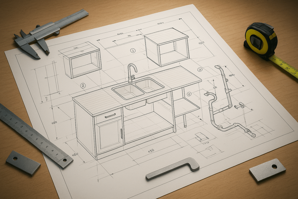
Shop drawings are created by contractors or vendors to illustrate specific components, such as cabinetry, prefabricated parts, and MEP systems. They focus on detailing how individual elements will be manufactured and installed.
Role in prefabrication and modular construction:
- Essential for producing accurate prefabricated parts.
- Help coordinate between designers, manufacturers, and site teams.
Difference between shop drawings and construction drawings:
- Construction drawings show the overall building design.
- Shop drawings focus on individual components and their installation.
➤ As-Built Drawings
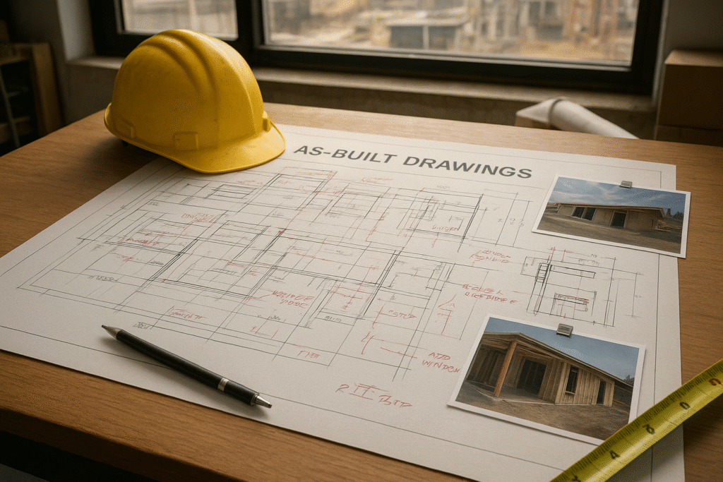
As-built drawings document the structure exactly as it was constructed, reflecting any modifications made during the project. They are typically prepared by contractors after completion.
Uses in maintenance, renovation, and facility management:
- Provide accurate records for future upgrades or repairs.
- Help facility managers plan renovations without design conflicts.
- Ensure compliance with safety and building standards.
Specialized Drafting Types in CAD
Beyond general construction drawings, specialized drafting types address more focused needs in architecture, interiors, furniture, and woodwork design.
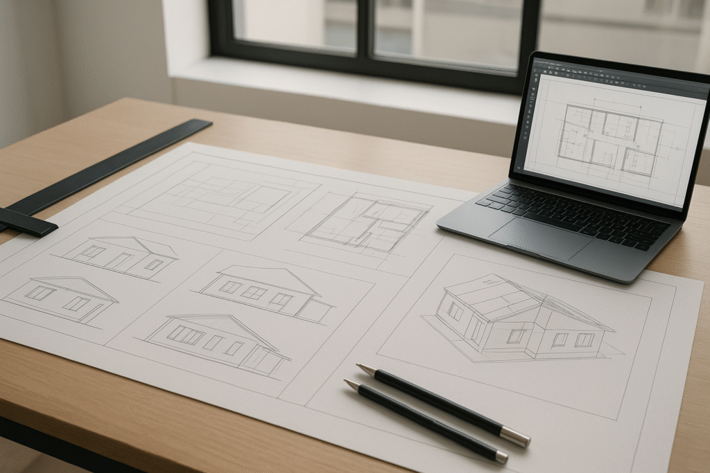
➤ Architectural Drafting
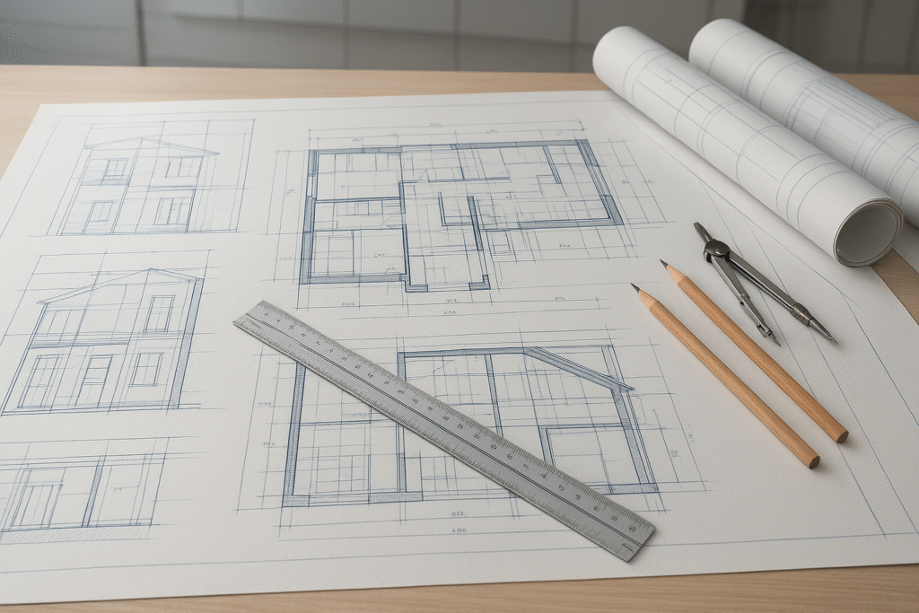
Architectural drafting includes site plans, floor layouts, elevations, and axonometric views. These drawings are essential for communicating design concepts to clients and investors, helping secure project approvals and visualize the overall structure before construction begins.
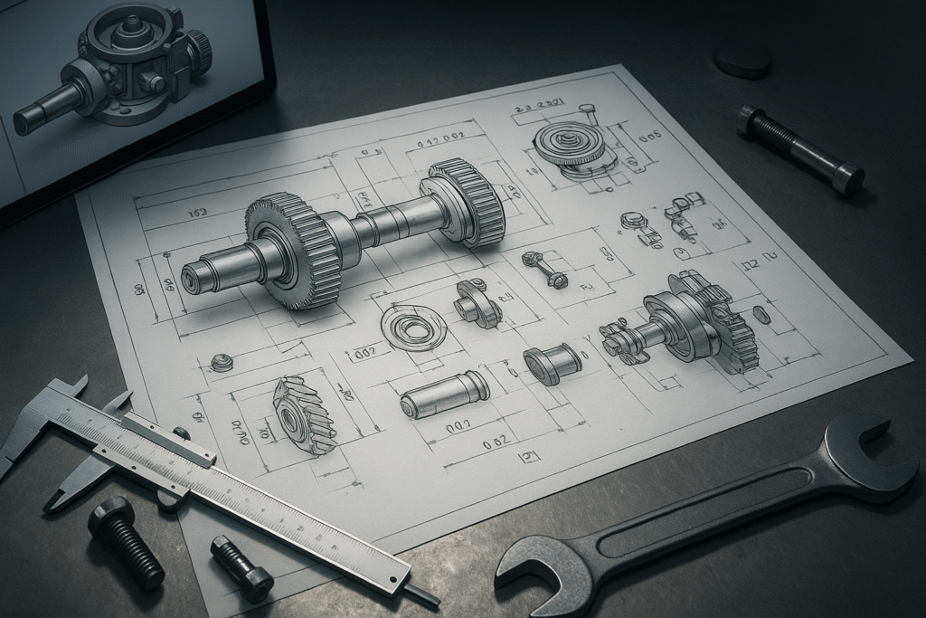
➤ Mechanical CAD Drawings
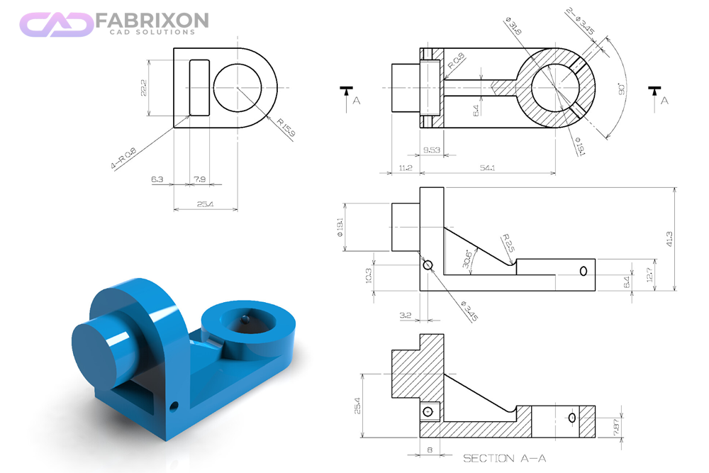
In mechanical engineering, CAD is used to design everything from small machine components to complex assemblies. Mechanical CAD drawings may include machine parts, assemblies, and technical schematics that define how products should be manufactured. These drawings provide detailed specifications such as tolerances, dimensions, and material requirements, making them crucial for the manufacturing and production process.
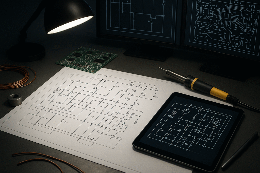
➤ Electrical CAD Drawings
Electrical CAD drawings are used to design and document electrical systems. They include wiring diagrams, circuit designs, and PCB (Printed Circuit Board) layouts. These drawings help engineers plan connections, identify components, and avoid costly wiring errors. From residential electrical plans to industrial control systems, electrical CAD drawings ensure safe and efficient power distribution.
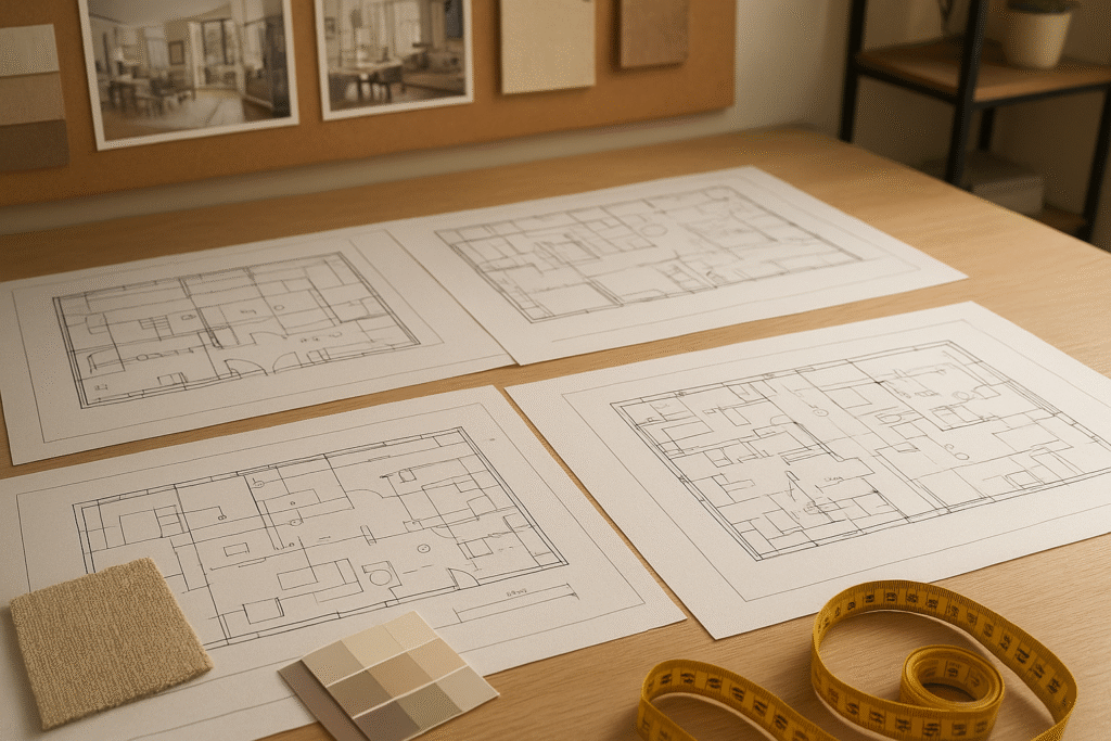
➤ Interior Drafting
Interior drafting focuses on details like ceiling plans, furniture layouts, lighting, and plumbing design. Clear interior drawings ensure contractors avoid structural mistakes, support safe renovations, and provide accurate material calculations to prevent cost overruns.
➤ Furniture Shop Drafting
Furniture shop drafting involves casework and millwork blueprints created for manufacturers. These drawings translate sketches into precise production documents, ensuring that custom furniture pieces fit perfectly within the space while maintaining both function and design accuracy.
➤ Millwork Drafting
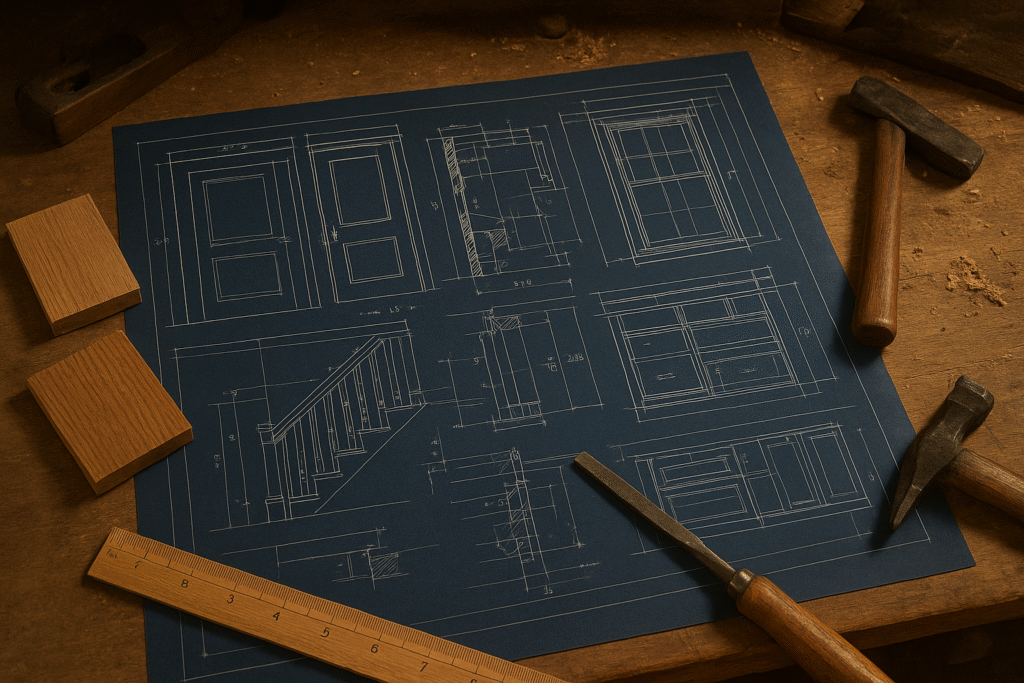
Millwork drafting covers detailed woodwork elements such as doors, windows, stairs, handrails, and cabinets. Because millwork requires precision, these CAD drawings provide exact measurements and cross-sections so contractors and craftsmen can deliver high-quality results.
Types of CAD Software for Drafting
Choosing the right CAD software depends on both the industry application and the functionality required for a project.
➤ By Industry Application
Architectural & Construction CAD Software
Tools like AutoCAD, Revit, and SketchUp are widely used to create floor plans, elevations, and BIM models. They support architects and contractors in drafting accurate building documentation.
Mechanical CAD (MCAD) Software
Programs such as SolidWorks, Inventor, and Creo focus on 3D modelling, simulations, and technical specifications for machines, automotive, and product design.
Electrical CAD (ECAD) Software
Specialized tools like SEE Electrical and Altium allow engineers to design PCB layouts, wiring diagrams, and electrical schematics, ensuring precise documentation for electronic systems.
➤ By Functionality
2D CAD Drawing Software
Used for creating technical drawings, schematics, and floor plans, 2D CAD software is ideal for industries where simple but accurate layouts are needed.
3D CAD Modelling Software
Enables designers to build realistic 3D models for construction, product design, and animation. Tools like Autodesk 3DS Max or ZBrush are often used in this category.
Parametric vs. Direct Modelling
- Parametric modelling links dimensions and features, allowing automatic updates when changes are made (e.g., in SolidWorks, FreeCAD, Onshape).
- Direct modelling gives more flexibility by editing shapes directly, making it useful for concept design and rapid prototyping (e.g., SketchUp, Blender, Tinkercad).
CAD Modelling Techniques
Different CAD modelling techniques are used depending on the project requirements, from simple 2D drafting to complex 3D simulations.
➤ 2D CAD Drafting Basics
2D CAD relies on geometric shapes like lines, arcs, and circles to produce technical drawings, floor plans, and schematics. It is widely used in architecture, construction, and engineering for quick and accurate layouts.
➤ 2.5D CAD and its Role in CNC Machining
2.5D CAD adds depth information to 2D geometry, making it useful for CNC machining and manufacturing. It allows designers to represent multiple flat surfaces at different heights, simplifying part production.
➤ 3D CAD for Realistic Modelling and Simulation
3D CAD creates lifelike models that include width, height, and depth. It enables detailed product design, building simulations, and engineering analysis, helping identify design issues early and improving visualization for clients. For example, Autodesk’s official guide on 3D modeling explains how architects and engineers use these tools for simulation, prototyping, and visualization.
➤ Wireframe, Surface, Solid & Hybrid Modelling
- Wireframe Modelling: Skeletal outlines for quick design concepts.
- Surface Modelling: Defines exterior surfaces for detailed, organic shapes.
- Solid Modelling: Provides complete internal and external geometry for simulations and stress tests.
- Hybrid Modelling: Combines surface and solid techniques to handle complex shapes not possible with one method alone.
Benefits of CAD Drawings in Construction & Design
Using CAD drawings in construction, architecture, and product design ensures precision and efficiency at every stage of a project.
➤ Improved Accuracy and Error Reduction
CAD drafting eliminates many of the errors common in manual drawings. With 2D and 3D CAD models, every floor plan, elevation, or MEP detail can be checked for consistency, reducing costly mistakes during construction.
➤ Faster Design Iterations and Approvals
CAD software allows quick modifications, making it easier to present multiple design options. This speeds up client approvals and streamlines collaboration between architects, engineers, and contractors.
➤ Cost Estimation and Resource Planning
Detailed CAD blueprints provide exact measurements and material requirements. This helps financial teams with budgeting, procurement, and resource allocation, ensuring projects stay within scope and cost limits.
How to Choose the Right CAD Software
Selecting the right CAD software depends on matching project needs with available tools and features.
➤ Factors: Project Scope, Budget, Learning Curve, Collaboration
When choosing CAD software, consider:
Project Scope: Large construction projects may need advanced tools like Revit or AutoCAD, while smaller tasks might work with QCAD or SketchUp
Budget: Free or low-cost options like FreeCAD suit beginners, while proprietary tools offer advanced features for professionals.
Learning Curve: Software such as SketchUp is easier to learn, whereas programs like SolidWorks or CATIA may require training.
Collaboration: Cloud-based platforms like Onshape enable real-time teamwork across design teams. Beginners exploring CAD can also check Top 11 Easiest Best Free CAD Software for Beginners in 2025 to find suitable tools for learning.
➤ Open Source vs Proprietary CAD Tools
Open Source CAD Software: Examples include FreeCAD, LibreCAD, and QCAD. These offer flexibility and no licensing cost, making them ideal for learners or small firms.
Proprietary CAD Software: Examples include AutoCAD, SolidWorks, and Revit. These provide advanced features, technical support, and industry-specific integrations, which are often necessary for professional and large-scale projects.
Conclusion:
Understanding the different types of CAD drawings, from construction and shop drawings to as-built documentation and specialized drafting, is essential for improving communication among engineers, contractors, and clients. Clear and precise CAD drafting reduces errors, lowers project costs, and ensures efficient execution across industries like architecture, construction, and manufacturing. At the same time, mastering these drawing types strengthens career skills for architects, designers, and engineers, making them more effective and competitive in today’s design-driven world.
Frequently Asked Questions(FAQ's)
Q1: What are the main types of CAD drawings?
The main types are construction drawings, shop drawings, and as-built drawings, with specialized drafting like architectural, interior, furniture, and millwork drafting.
Q2: What are construction drawings in CAD?
Construction drawings are official contract documents that include floor plans, elevations, sections, and MEP details, guiding the entire building process.
Q3: What is the difference between construction drawings and shop drawings?
- Construction drawings show the overall design of the building.
- Shop drawings detail individual components (e.g., cabinetry, prefabricated parts, MEP systems) and their installation.
Q4: What are as-built drawings in CAD?
As-built drawings record the building exactly as it was constructed, reflecting changes made during the project. They are essential for maintenance, renovations, and facility management.
Q5: What is architectural drafting in CAD?
Architectural drafting covers site plans, layouts, elevations, and axonometric views used for client approvals and design visualization.
Q6: What is interior drafting in CAD?
Interior drafting includes ceiling plans, furniture layouts, lighting, and plumbing design to ensure safe, accurate, and cost-effective renovations or new builds.
Q7: What software is best for different CAD drawings?
- AutoCAD, Revit, SketchUp: architectural & construction.
- SolidWorks, Inventor, Creo: mechanical CAD (MCAD).
- SEE Electrical, Altium: electrical CAD (ECAD).
Q8: What is the difference between 2D CAD and 3D CAD?
- 2D CAD: flat technical drawings like floor plans or wiring diagrams.
- 3D CAD: lifelike models for simulation, product design, and visualization.
Q9: Why are CAD drawings important in construction and design?
They improve accuracy, reduce errors, speed up approvals, support cost estimation, and ensure better collaboration across project teams.
Q10: What is millwork drafting in CAD?
Millwork drafting provides precise drawings for doors, windows, stairs, and custom woodwork, ensuring accurate fabrication and installation.